Mini Tutorial - Analog Devices
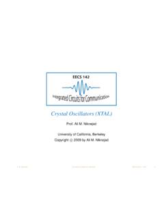
this series of mini tutorialsto build the filter, but be aware of whether the BP inverts the phase or not. In addition, be aware ... resonant frequency should be at least 20 dB. Also, since there is a capacitor in the feedback network, a current feedback amplifier is probably not appropriate.
Download Mini Tutorial - Analog Devices

Information
Domain:
Source:
Link to this page:
Documents from same domain

AD743 Ultralow Noise BiFET Op Amp Data Sheet …
www.analog.comREV. E Information furnished by Analog Devices is believed to be accurate and reliable. However, no responsibility is assumed by Analog Devices for its

MT-070: In-Amp Input RFI Protection - Analog …
www.analog.comRev.0, 10/08, WK Page 1 of 6 MT-070 TUTORIAL In-Amp Input RFI Protection . PROTECTING IN-AMPS AGAINST RFI . Real-world applications must deal with an ever increasing amount of radio frequency

LTC3108 - Ultralow Voltage Step-Up Converter and …
www.analog.comLTC3108 3108fc For more information www.linear.com/LTC3108 LDO

1.8 V Low Power CMOS Rail-to-Rail Input/Output …
www.analog.com1.8 V Low Power CMOS Rail-to-Rail Input/Output Operational Amplifier Data Sheet AD8515 Rev. E Document Feedback Information furnished by Analog Devices is believed to be accurate and reliable.

Low Cost Micropower, Low Noise CMOS Rail-to …
www.analog.comLow Cost Micropower, Low Noise CMOS Rail-to-Rail, Input/Output Operational Amplifiers Data Sheet AD8613/AD8617/AD8619 Rev. H Document Feedback Information furnished by Analog Devices is believed to be accurate and reliable.

Low Cost CMOS, High Speed, Rail-to-Rail Amplifiers
www.analog.comLow Cost CMOS, High Speed, Rail-to-Rail Amplifiers Data Sheet ADA4891-1/ADA4891-2/ADA4891-3/ADA4891-4 Rev. F Document Feedback Information furnished by Analog Devices ...

Zero-Drift, Single-Supply, Rail-to-Rail Input/Output ...
www.analog.comZero-Drift, Single-Supply, Rail-to-Rail Input/Output Operational Amplifier Data Sheet AD8628/AD8629/AD8630 FEATURES Lowest auto-zero amplifier noise Low offset voltage: 1 µV AD8628

FEATURES DESCRIPTIO U - analog.com
www.analog.com1 LT1025 1025fb DESCRIPTIO U APPLICATIO S U 80µA Supply Current 4V to 36V Operation 0.5°C Initial Accuracy (A Version) Compatible with Standard Thermocouples (E, J, K, R, S, T) Auxiliary 10mV/°C Output Available in 8-Lead PDIP and SO Packages Thermocouple Cold Junction Compensator Centigrade Thermometer Temperature …

LT1173 - Micropower DC/DC Converter Adjustable …
www.analog.comLT1173 1 Micropower DC/DC Converter Adjustable and Fixed 5V, 12V VOUT 5V/DIV 0V PROGRAM 5V/DIV 5ms/DIV 1173 TA02 L1* 100µH LT1173 • TA01 + GND SW2 FB SW1 ILIM VIN 10 F LT1173

AD9850 CMOS, 125 MHz Complete DDS …
www.analog.comrev. h a cmos, 125 mhz complete dds synthesizer ad9850 functional block diagram clock out clock out analog in analog out dac rset …
Related documents

RLC Resonant Circuits - University of Cambridge
mlg.eng.cam.ac.ukFigure 2: Series RLC circuit Figure 2 shows a series resonant RLC circuit. The total impedance in the circuit is given by, Z total = R + Z L + Z C = R + j(X L + X C) = R + j !L 1!C (4) (5) Figure 3 shows how the total impedance changes with frequency Figure 1 shows that the absolute reactances of Figure 3: Magnitude and phase of impedance in a ...
Crystal Oscillators (XTAL) - University of California ...
rfic.eecs.berkeley.eduSeries and Parallel Mode C 0 L 1 C 1 R 1 C 0 L 1 R 1 low resistance high resistance Due to the external physical capacitor, there are two resonant modes between a series branch and the capacitor. In the series mode ωs, the LCR is a low impedance (“short”). But beyond this frequency, the LCR is an equivalent inductor that resonates
Series 3000 Cooling Tower
baltimoreaircoil.com43 Resonant Speed Identification Procedure PART 8 New Field Connections for TriArmor® Corrosion Protection System Cold Water Basin 45 Installation Instructions OPERATION & MAINTENANCE » SERIES 3000 COOLING TOWER 1 WWW.BALTIMOREAIRCOIL.COM. 2 WWW.BALTIMOREAIRCOIL.COM DANGER

Oscillator Circuits
sites.science.oregonstate.eduCrystal Resonant Frequencies The crystal has two resonant frequencies: Series resonant: RLC determine the resonant frequency. The crystal has a low impedance. Parallel resonant:RL and CM determine the resonant frequency. The crystal has a high impedance. The series and parallel resonant frequencies are very close, within 1% of each other.

Quality factor, Q - UC Santa Barbara
web.ece.ucsb.eduIf we consider an example of a series resonant circuit. At resonance, the reactances cancel out leaving just a peak voltage, Vpk, across the loss resistance, R. Thus, Ipk = Vpk/R is the maximum current which passes through all elements. Then, R RC …
Introduction to Microstrip Antennas - University of Houston
courses.egr.uh.eduHowever, the Q of the resonant cavity mode also increases, making the patch currents stronger at resonance. These two effects cancel, allowing the patch to radiate well even for thin substrates (though the bandwidth decreases). 31 A microstrip antenna can radiate well, even with a …

Filter Circuits - Northern Illinois University
nicadd.niu.eduSeries RLC Circuit † An RLC circuit can form a notch filter that only negates a narrow band of frequency. † The series impedance can be calculated and inserted to find the gain. † The width of the filtered region is the Q value. † A graph of the behavior shows the notch. R L v out Z LC RZ+ LC----- -v v out = in v in C Z LC 1 ⁄ωj Cj+ ...

Frequency response: Resonance, Bandwidth, Q factor
ocw.mit.eduThe bandwidth is the difference between the half power frequencies Bandwidth =B =ω2−ω1 (1.11) By multiplying Equation (1.9) with Equation (1.10) we can show that ω0 is the geometric mean of ω1 and ω2. ω0= ωω12 (1.12) As we see from the plot on Figure 2 the bandwidth increases with increasing R. Equivalently the sharpness of the resonance increases with decreasing R.
Chapter 5 Capacitance and Dielectrics
web.mit.eduresistors, filtering out unwanted frequency signals, forming resonant circuits and making frequency-dependent and independent voltage dividers when combined with resistors. Some of these applications will be discussed in latter chapters. Figure …

AC CIRCUITS: RLC SERIES CIRCUIT INTRODUCTION
www.austincc.eduJul 11, 2007 · These values have been chosen so that the resonant frequency of the series RLC circuit will be about 12,000 Hz in the HIGH frequency version and 1100 Hz in the LOW . 8D-RLC Series Circuit 07-07-11.doc - 2 - frequency version. The circuit component values have been specifically chosen to