Transcription of Small Magnetic Loop Antenna Project
1 WA4 MNT Small Transmitting Magnetic Loop Antenna Project 30m, 20m, 17m, 15m, 12m, 10m Bands With the solar cycle improving, I wanted to build an efficient HF Antenna for the upper bands that I could easily throw in the trunk of the car and operate quickly with a minimum of setup time. I decided on a Small Magnetic loop Antenna after researching the subject on the web and reading the following statement from VK5 KLT s article on Small Magnetic loop antennas. A properly designed and constructed Small loop of nominal 1m diameter will outperform any Antenna type except a tri-band beam on the 10m/15m/20m bands, and will be within an S-unit (6db) or so of an optimised mono-band 3-element beam that s mounted at an appropriate height above ground.
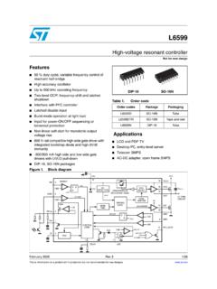
2 There is a wealth of information on Small Magnetic loop Antenna construction on the web. One of the best sources I found was by AA5TB, , and VK5 KLT, . The Antenna I built is a compilation of ideas I borrowed from many sources, gleaned from the work of others, and a little redesign. This Project resulted in a three foot diameter copper loop mounted on a Small pedestal, with continuous coverage of 30m through 10m bands (10 MHz-30 MHz). I have been able to obtain an SWR of 1:1 - :1 over the entire range.
3 Based on the advice of the most successful builders, I chose copper as the metal of choice and all joints are silver soldered to reduce the interconnection resistance. I chose to design my own trombone style capacitor (~10pF - ~110pF), and shielded Faraday Loop input. I used copper tubing, readily available low loss dielectric materials, PEX (cross linked polyethylene) tubing for the capacitor insulator, UHMW plastic (Polypropylene) for all other RF exposed parts, and non Magnetic hardware for all mechanical fastening. My design was based on AA5TB s on-line calculator, , and my dielectric spacing exceeds a 2KW rating.
4 I chose to mount my portable loop, a little less than one diameter, off the ground, from the bottom of the loop, with six radials, two loop diameters long, from the base. These antennas are high-Q resonant circuits. Many kilovolts can be present across the capacitor, and produce concentrated electro- Magnetic radiation even at low power levels. For safety, maintain a minimum of 6 feet away from the Antenna , while transmitting. I have access to milling and lathe equipment, so my exact approach may not be suitable for many amateurs; however many good designs are available using butterfly or vacuum capacitors and easier available tools.
5 Even simpler monoband designs may be more appropriate. I incorporated a motor drive for remote tuning with a wired control cable. With the Antenna bandwidth being so narrow, tuning for maximum receiver noise yields almost optimum SWR. I use no Antenna tuner between the radio and Antenna . I am not an Antenna theoretician; my expertise is in mechanical design. I have attached all my detailed .pdf s and defer to the complete VK5 KLT An Overview of the Underestimated Magnetic Loop HF Antenna article at the end of this document for the theory of operation.
6 Results using my MFJ-259B Antenna analyzer: 10m - SWR : 1 R=53, X=10 SWR : 1 R=46, X=8 12m SWR : 1 R=56, X=9 15m SWR 1 : 1 R=47, x=0 SWR 1 : 1 R=43, X=0 17m SWR : 1 R=43, X=7 20m SWR : 1 R=43, X=0 SWR : 1 R=44, X=0 30m SWR : 1 R=50, X=8 Small Magnetic loops typically have 5 dBi gain when used with two loop diameter length radials.
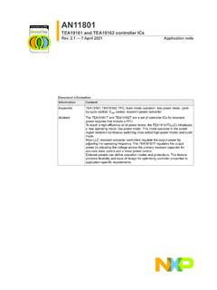
7 They exhibit a vertically polarized signal at the horizon and horizontally polarized signal overhead. Thank you to all the amateurs that have shared their wisdom and made the information public on the internet to make this Project a success. You may consider joining the Yahoo groups, MagneticLoopAntenna or MagLoop Ken - WA4 MNT E-mail Trombone style capacitor ~10pF ~110pF Shielded Faraday input loop Trombone capacitor gear drive Using a , #16816MD, 24 vdc, 40 rpm gearmotor Frequency scale Base with thumbscrews for 6 radials, and surplus fiberglass mast section.
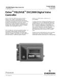
8 Motor controller and cables 12v gel cell transceiver supply, with 12v to 24v switching supply DC-DC module, for the gearmotor drive Set up for operation Small enough to fit in the trunk of my Toyota Corolla 12v -24v switcher for gearmotor Motor controller , direction and speed , #16816MD, 24v, 40 rpm gearmotor Common Plastics Dissipation Factor Chart This will aid you in selecting suitable plastics for loop construction. Look for plastics with low dissipation factors.
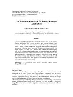
9 G10 /G11 glass epoxy board have a poor dissipation factor, , similar to PVC. UHMW (Polypropylene) is one tenth the cost of PTFE (Teflon). 2B134786521347865 ACDBACD LOOP_ASSYSHEET 1 OF 33RD # - BSCALE: # NOT # 3' Small MAGNETICLOOP Antenna 30m-10mTITLEENG: WA4 MNTX # BOX 956 CLARKDALE, AZ 86324928-639-3481 (VOICE) INFORMATION CONTAINED IN THISDOCUMENT IS THE PROPERTY OFBENT RIVER MACHINE AND SHALL NOT BE USEDOR DISCLOSED OUTSIDE OF BENT RIVER MACHINEWITHOUT WRITTEN AUTHORIZATIONANG. # - INCHESUNLESS SPECIFIEDTOLERANCES ARE:BYDATEDESCRIPTIONECOREVKL08/08/10 INITIAL RELEASE NOTES:ALL COPPER Antenna ELEMENTS JOINED BY SILVER SOLDERANY FASTENERS USED MUST BE 300 SERIES HEIGHT IS TWO LOOP DIAMETERS ABOVE GROUNDOPTIMUM RADIALS ARE ~2 LOOP DIAMETERS LONGTHESE ANTENNAS ARE HIGH-Q resonant KILOVOLTS CAN BE PRESENT ACROSS THE CAPACITOR,AND PRODUCE CONCENTRATED ELECTRO-MAGNETICRADAITION EVEN AT LOW POWER LEVELS.
10 FOR SAFETY,MAINTAIN A MINIMUM OF 6' AWAY FROM THE ANTENNAWHILE !!!TROMBONE STYLECAPACITOR`15pF - 80pFSEE DETAIL ASEE DETAIL BSEE DETAIL CSEE DETAIL " FIBERGLASS MAST SECTION(MILITARY SURPLUS)ALUMINUM BASE PLATESEE DETAIL ASEE DETAIL BSEE DETAIL CSEE DETAIL D2B134786521347865 ACDBACD LOOP_ASSYSHEET 2 OF 33RD # - BSCALE: # NOT # 3' Small MAGNETICLOOP Antenna 30m-10mTITLEENG: WA4 MNTX # BOX 956 CLARKDALE, AZ 86324928-639-3481 (VOICE) INFORMATION CONTAINED IN THISDOCUMENT IS THE PROPERTY OFBENT RIVER MACHINE AND SHALL NOT BE USEDOR DISCLOSED OUTSIDE OF BENT RIVER MACHINEWITHOUT WRITTEN AUTHORIZATIONANG.