Dc converter with constant current loop
Found 7 free book(s)
LM5164 100-V Input, 1-A synchronous buck DC/DC converter ...
www.ti.comLM5164 100-V Input, 1-A synchronous buck DC/DC converter with ultra-low IQ 1 1 Features 1• Designed for reliable and rugged applications – Wide input voltage range of 6 V to 100 V – Junction temperature range: –40°C to +150°C – Fixed 3-ms internal soft-start timer – Peak and valley current-limit protection
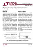
AN149 Modeling and Loop Compensation Design of …
www.analog.comSince the current and voltage sources are the products of two variables, the system is still a nonlinear system. SmAll SIgnAl modelIng of PWm ConVerter PoWer StAge A switching mode power supply (SMPS), such as the buck step-down converter in Figure 4, usually has two operating modes, depending on the on/off state of its main control switch.

Snubber Circuits Suppress Voltage Transient Spikes in ...
pdfserv.maximintegrated.comloop due to (dv/dt) induced spurious turn-on of the MOSFET as a result of the transient voltage spike. Secondary Leakage Inductance and the Rectifier Diode The transformer secondary leakage inductance may couple with the reverse recovery current IREC of the output rectifier diode to cause ringing when the diode turns off.
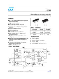
High-voltage resonant controller
www.st.comThe IC enables the designer to set the operating frequency range of the converter by means of an externally programmable oscillator. At start-up, to prevent uncontrolled inrush current, the switching frequency starts from a programmable maximum value and progressively decays until it reaches the steady-state value determined by the control loop.

Zero Voltage Switching Resonant Power Conversion
www.ti.comvalue L, and the magnetizing current ML., as well as the inductor’s DC resistance is negligi-ble. In addition, both the input voltage VjN and output voltage V. are purely DC, and do not vary during a given conversion cycle. Last, the converter is operating in a closed loop configu-ration which regulates the output voltage V. .
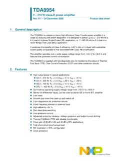
TDA8954 2 × 210 W class-D power amplifier - NXP
www.nxp.compop noise-free start-up. The bias-current setting of the (VI converter) input stages is related to the voltage on the MODE pin. In Mute mode, the bias-current setting of the VI converters is zero (VI converters are disabled). In Operating mode, the bias current is …

Building a DC-DC Step-Down (Buck) Converter Circuit Using ...
www.egr.msu.eduThe primary objective is to build a simple circuit of DC-DC stepping-down (Buck) converter. With the LM7809 positive voltage regulator, it is expected to have about 11V-17V DC input stepping-down to 9V DC output. And the secondary objective is to be able to achieve output voltage that is stabilized at its level.