Esd Test Methods
Found 10 free book(s)
FAILURE MECHANISM BASED STRESS TEST QUALIFICATION …
www.aecouncil.comMIL-STD-750 Test Methods for Semiconductor Devices 1.2.2 Industrial UL-STD-94 Test for Flammability of Plastic Materials of Parts in Devices and Appliances. JEDEC JESD-22 Reliability Test Methods for Packaged Devices J-STD-002 Solderability Tests for Component Leads, Terminations, Lugs, Terminals and Wires.
MIL-STD-750D, Test Methods for Semiconductor Devices
www.navsea.navy.milTest methods numbered 5000 to 5999 inclusive are for high reliability space applications. 1.2.2 Revisions. Revisions are numbered consecutively using a period to separate the test method number and the revision number. For example, 4001.1 is the first revision of test method 4001. 1.3 Method of reference.

AN3353 Application note - STMicroelectronics
www.st.comtest methods, and the specified levels are most of the time the maximum standard levels. ... ESD test bench for STMicroelectronics protection devices Our device is soldered on a dedicated PCB as shown in Figure 3. A 2 mm female banana plug is connected to the ground plane of the PCB. This plug, through the bleeder resistors (2

MAY 1999 JOINT INDUSTRY STANDARD - Naval Sea Systems …
www.navsea.navy.milCracking Task Group, B-10a, and the JEDEC JC-14.1 Committee on Reliability Test Methods for Packaged Devices.) 1 Foreword The advent of surface mount devices (SMDs) introduced a new class of quality and reliability concerns regarding package cracks and delamination. This document describes the standardized levels of floor life

Charged Device Model (CDM) – Component Level
www.esd-resource.comdischarge (ESD) sensitivity of components to the defined charged device model (CDM). 1.2 Purpose The purpose of this document is to establish a test method that simulates CDM failures and provides reliable and repeatable results from tester to tester. This will allow accurate comparisons of component CDM ESD sensitivity levels.
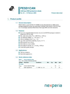
PESD1CAN CAN bus ESD protection diode
assets.nexperia.comCAN bus ESD protection diode Fig 7. ESD clamping test setup and waveforms 006aaa259 50 Ω RZ CZ D.U.T. (Device Under Test) vertical scale = 200 V/div horizontal scale = 50 ns/div unclamped +1 kV ESD voltage waveform (IEC 61000-4-2 network) clamped +1 kV ESD voltage waveform (IEC 61000-4-2 network) unclamped −1 kV ESD voltage waveform (IEC ...

PESD2CAN CAN bus ESD protection diode - Nexperia
assets.nexperia.comCAN bus ESD protection diode Fig 9. ESD clamping test setup and waveforms 006aaa941 50 Ω RZ CZ D.U.T. (Device Under Test) unclamped +8 kV ESD pulse waveform (IEC 61000-4-2 network) clamped +8 kV ESD pulse waveform (IEC 61000-4-2 network), Pin 1 to 3 unclamped −8 kV ESD pulse waveform (IEC 61000-4-2 network) clamped −8 kV ESD voltage waveform
Charged Device Model (CDM) Qualification Issues - JEDEC
www.jedec.org< 250V •Basic ESD control methods with grounding of metallic machine parts and control of insulators + •Process specific measures to reduce the charging of the device OR to avoid a hard discharge (high resistive material in contact with the device leads). V CDM < 125V •Basic ESD control methods with grounding of metallic machine

PESD1LIN LIN-bus ESD protection diode - Nexperia
assets.nexperia.comLIN-bus ESD protection diode Fig 5. ESD clamping test setup and waveforms 006aaa166 50 Ω RZ CZ vertical scale = 200 V/div horizontal scale = 50 ns/div unclamped +1 kV ESD voltage waveform (IEC 61000-4-2 network) clamped +1 kV ESD voltage waveform (IEC 61000-4-2 network) unclamped −1 kV ESD voltage waveform (IEC 61000-4-2 network)
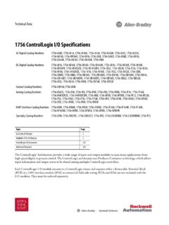
1756 ControlLogix I/O Specifications
literature.rockwellautomation.com6 Rockwell Automation Publication 1756-TD002M-EN-E - December 2019 1756 ControlLogix I/O Specifications On-state current, min 5 mA @ 74V AC On-state current, max 16 mA @ 132V AC Inrush current, max 250 mA Input impedance, max 8.25 kΩ @ 132V AC, 60 Hz