Fan Powered Terminal
Found 8 free book(s)
TACO ZONE CONTROLS WIRING GUIDE
www.taco-hvac.comALTERNATIVE WIRING (24 VAC POWERED INPUT SIGNAL) H N REMOVE JUMPER. DO NOT CONNECT POWER TO N AND H TERMINALS. 24 VAC SIGNAL STAT LIGHT WILL GO ON AND OFF WITH 24 VAC SIGNAL. POWER LIGHT WILL ALWAYS BE OFF. Note: When using Alternative Wiring diagram, the boiler oper- ating control’s ZC terminal will see the load of the circulator(s). Warning:

with Equipment Interface Module Installation Guide
customer.honeywell.comsettings for Fan or System Heat/Cool. Menu. Select options to: set schedules, view equipment status, change IAQ ... Terminal Description Terminal Description C Common wire from 24 VAC transformer. C Common wire from 24 VAC ... powered by the system trans-former. Do NOT install a field jumper if the stage of heating has its own transformer. 1 2 ...

D4120W Watertight Duct Smoke Detector - System Sensor
www.systemsensor.com• Patented interconnect feature for multi-fan shutdown • New high contrast terminal designations ... Terminal connections shall be of the strip and clamp method suitable for 12–18 AWG wiring. ... all interconnected units must be powered using the same independent supply.

How We Calculate MCA and MOP - Titus HVAC
www.titus-hvac.comMinimum Circuit Ampacity (MCA) for both fan-powered and heater-only products is calculated with the following equation: MCA = 1.25 x [Motor Rated Current + Heater Current] ... high-current test conditions of the complete terminal unit, in accordance with UL1995. The FLA on
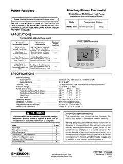
Blue Easy Reader Thermostat - Emerson Electric
climate.emerson.comG Fan Relay RC Power for Cooling RH Power for Heating C "Common wire from secondary side of cooling (Optional). Required for fault indication, continuous backlight operation or remote temperature sensor operation" 6 Powered closed 3rd wire for 3-wire zone valve No Output No Output No Output W/E Heat Mode Heat Mode 1st Stage Heat Mode 2nd Stage,
ANSI/ASHRAE/IES Standard 90.1-2016 Performance Rating ...
www.pnnl.govFigure 8. Single Maximum Control Sequence for Parallel Fan Powered VAV with Reheat Boxes ..... 3.112 Figure 9. SAT Cooling Setpoint Reset based on Outdoor Air Temperature (OAT) ..... 3.140 Figure 10. Example of SAT Heating Setpoint Reset based on Outdoor Air Temperature. ..... 3.142 Figure 11.
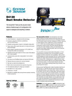
D4120 Duct Smoke Detector - System Sensor
www.systemsensor.comterminal designations make wiring easy. With its 2:1 sensor-to-power capability, the power board of the D4120 may be used to monitor a second sensor, D4S, simultaneously (i.e., supply and return side). As many as 50 InnovairFlex detectors can be interconnected. When one unit senses smoke, all interconnected detectors will switch

Product Catalog Packaged Rooftop Air Conditioners ...
www.trane.comMulti-Speed Indoor Fan System Multi-speed indoor fan system is designed for use in applications for meeting the minimum requirement of CA Title 24. This system incorporates a multi-speed fan control to change the speed of the fan to 67% of full airflow based off compressor stages. Stainless Steel Heat Exchanger