Flange dimensions din
Found 10 free book(s)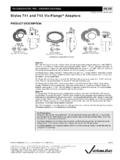
Styles 741 and 743 Vic-Flange Adapters
www.garitec.com06.06 Styles 741 and 743 Vic-Flange Adapters 3 DIMENSIONS VIC-FLANGE ADAPTER NOTES 1 The Style 741 (2 - 12"/50 - 300 mm) design incorporates small teeth …
DIN-2633 - san-chuen.com.tw
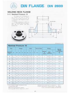
www.san-chuen.com.twDIN FLANGE WELDING NECK FLANGE 3-1). Nominal Pressure 16 The flanges with the dimensions of this standard and made of St. 37-2 material can be used at maximum 120

R Circular sightglass fittings to DIN 28120 or similar ...
www.maxmuellerag.comOur circular sightglass fittings to be mounted directly onto a welding flange, pad or similar correspond in their con-struction and assembly to the dimensions and constructional guidelines of the DIN specification 28121.
Dimensions, Sizes and Specification of DIN Flange & DIN ...
gttrade.byP N25/25BAR Dimensions, Sizes and Specification of DIN Flange & DIN Standard Flanges Pressure Rating from PN6 to PN 40 Slip On Flanges Blind Flanges Welding Neck Flanges
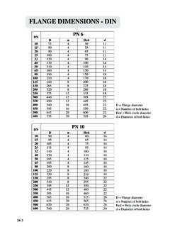
FLANGE DIMENSIONS - DIN - Shipserv
www.shipserv.com24: FLANGE DIMENSIONS - JIS D = Flange diameter n = Number of bolt holes Hcd = Hole circle diameter d = Diameter of bolt holes JIS 5K JIS 10K JIS 16K JIS 20K
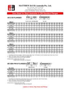
MATTHEW DAVIS Australia Pty. Ltd.
www.matthewdavis.com.auFLANGE ASME B16.5 FORGED FLANGES CLASS 150 Nominal Bore Size 15 20 25 32 40 50 65 80 100 125 150# 200# 250 300 350 400 450 500 600 OD OF FLANGE 90 100 110 120 130 150 180 190 230 255 280 345 405 485 535 600 635 700 815
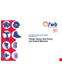
fwb Tech & Download Content www.fwb.co.uk Flange Tables ...
www.fwb.co.uk3 Flange Tables, Bolt Sizing and Gasket Materials There are many different standards relating to the sizing and specification of flange & bolt sets world-wide, …
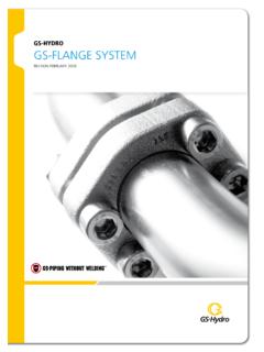
GS-HYDRO GS-FLANGE SYSTEM
www.gshydro.comPRODUCT CATALOGUE GS-FLANGE SYSTEM – INTRODUCTION 4 GS Flange connections Retain Ring System The GS Retain Ring system is used for piping with a maximum
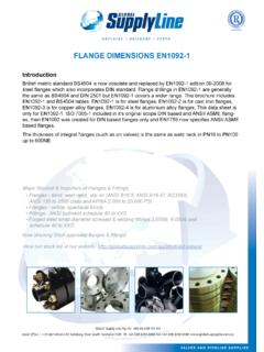
FLANGE DIMENSIONS EN1092-1 - Global Supply Line
globalsupplyline.com.au3 global supply line Ø pipe d1 m dn iso iso d a iso c h b h1 e r s f bolts n° holes kg 10 17,2 18 90 60 28 40 35 16 6 2 4 1,8 14 m12 4 0,5 15 21,3 22,5 95 65 32 45 38 16 6 2 4 2,0 14 m12 4 1,0 20 26,9 28 105 75 40 58 40 18 6 2 4 2,3 14 m12 4 1,0 25 33,7 34,5 115 85 45 68 40 18 6 2 4 2,6 14 m12 4 1,0
API - Sensor
www.sensor.siOptions 99/01 Contents Chapter/Page Applications, General design features 00/02 Valve finder 00/03 How to use: Signs and symbols, Flange drillings and facings