Function Diagrams
Found 6 free book(s)
CF 500, CF 600 Circuit Diagrams
bodybuilder.navistar.comsymbol or function by finding the corresponding number under the component name. Circuit Function Identifiers (7) Some components without internal schematics use symbols or text to describe the function of a circuit in a system.

Transfer Function Models of Dynamical Processes
chemeng.queensu.caBlock Diagrams Transfer ... Transfer function typically written as rational function of polynomials where and can be factored following the discussion on partial fraction expansion s.t. where and appear as real numbers or complex conjuguate pairs. 66 Poles and zeroes Definitions: ...

Sample of UML Diagrams for ATM System
groups.umd.umich.eduSample of UML Diagrams for ATM System For Data: Class diagram Class Diagram:-Class diagrams describe the static structure of a system, or how it is structured rather than how it behaves. These diagrams contain the following elements: 1. Classes , which represent entities with common characteristics or features. These features include

Use Case Diagrams - Pace
csis.pace.eduUse Case Descriptions • actors - something with a behavior or role, e.g., a person, another system, organization. • scenario - a specific sequence of actions and interactions between actors and the system, a.k.a. a use case instance • use case - a collection of related success and failure scenarios, describing actors using the system to
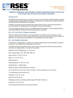
TERMINAL MARKINGS AND INTERNAL WIRING …
www.rses.orgor function of the windings which are brought to the terminal.* The following letters and symbols shall be used for motors and generators and their auxiliary devices when they are included within or mounted on the machine.* Resistance (shunt field adjusting)–V1, V2, V3, etc. Shunt braking resistor–DR1, DR2, DR3, DR4, etc.

Diagrams, Device Designations, and Symbols for Industrial ...
forums.autodesk.comgraphic symbol: Symbols used on single-line (one-line) diagrams, on schematic or elementary diagrams, or, as applicable, on connection or wiring diagrams. Graphic symbols are correlated with parts lists, descriptions, or instructions by means of device designations. interconnection diagram: A diagram that shows only the external connections between