Installation Manual Diaphragm Well Tank
Found 8 free book(s)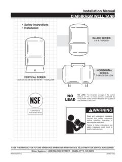
Installation Manual DIAPHRAGM WELL TANK
www.americanwaterheater.cominstallation manual keep this manual for future reference whenever maintenance adjustment or service is required. printed 0712 205621-002 diaphragm well tank vertical series: 14-20-25-32-36-52-65-86-96-119 gallon in-line series: 2-5 & 7 gallon horizontal series: 7-14 & 20 gallon ˘ ˘ ˇ ˆ˘˘ ˙˝ˇ ˛ ˚ no lead
Tank Installation and Operation Manual
www.globalwatersolutions.comFig. 1.4-1 Tank Installation with Accessories Tranducer Flow Sensor Pressure Switch Pressure Gauge Relief Valve Water Flow Tank • This is a diaphragm type pressure tank for use on a well water or booster system. The system must be protected by a suitable relief valve. • FlowThru™ Series tanks should only be used in Variable
RosemountTM 3051S Pressure Transmitter
www.emerson.comfor manual sampling. By complementing the high-accuracy level measurement with high-performance temperature and pressure measurement, the density and mass of the product in the tank as well as the net volume can be continuously calculated. Rosemount 3051S is the standard pressure transmitter for Rosemount Tank Gauging Systems:
PMC51, PMP51, PMP55 - Endress+Hauser
portal.endress.comFig. 1: Installation above the diaphragm seal P01-PMP75xxx-05-xx-xx-en-011 Fig. 2: Diagram of maximum installation height above the diaphragm seal for vacuum applications, depending on the pressure at the diaphragm seal H1 0.0 2.0 4.0 6.0 8.0 10.0 12.0 50 100 200 300 400 500 600 700 800 900 1000 Inert oil High temperature oil Vegetableoil ...

Dry System Technical Manual for Operation, Maintenance …
www.vikinggroupinc.comThis technical manual will cover the Viking dry pipe valve, its trim parts, and their func-tions as well as describe the operation, main-tenance, and repair of valves and system devices. Viking dry pipe valves are available in three configurations; the Model F-1, F-2, or Model G Series Dry Pipe Valves (Figure 2).
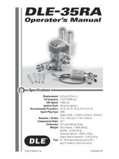
DLE-35RA
manuals.hobbico.comMake sure the fuel line is well-secured to the engine and to the fuel tank so that it won’t come off in fl ight. Do not use silicone fuel line because it will be dissolved by the fuel. Use gasoline approved rubber fuel line. Always secure the fuel line away from the cylinder head. The engine’s heat can damage the fuel line.
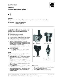
Type 4708 Supply Pressure Regulator
www.samsongroup.comInstallation To avoid the formation of excessive condensate, the supply pressure regulator is to be installed as closely as possible to the compressor or the compressed air tank. The regulator is either mounted directly in the pipeline or into the appropriate panel cut-out. In addition, it may be attached directly to the

Cerabar S PMC71, PMP71, PMP75 (Technical Information)
portal.endress.comCeramic process isolating diaphragm used for PMC71 (Ceraphire®) The ceramic sensor is a dry sensor, i.e. the process pressu re acts directly on the robust ceramic process isolating diaphragm and deflects it. A pressure-dependent change in capacitance is measured at the electrodes of the ceramic carrier and the process isolating diaphragm.