Lab 2 Simple Electric Circuits
Found 10 free book(s)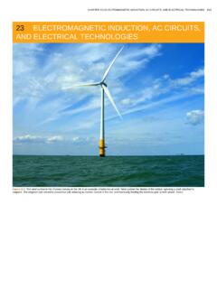
23 ELECTROMAGNETIC INDUCTION, AC CIRCUITS, AND …
www.wright.edu• Explain how various modern safety features in electric circuits work, with an emphasis on how induction is employed. ... • Calculate current and/or voltage in simple inductive, capacitive, and resistive circuits. 23.12.RLC Series AC Circuits ... (You can also observe this in a physics lab.) Each time the switch is opened, the galvanometer ...
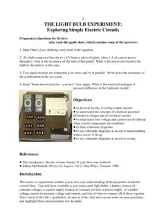
1 THE LIGHT BULB EXPERIMENT: Exploring Simple Electric ...
faraday.physics.utoronto.caExploring Simple Electric Circuits Preparatory Questions for Review: (also read this guide sheet, which contains some of the answers!) 1. State Ohm’s Law, defining every term in the equation. 2. If a bulb connected directly to a 6 V battery glows brightly when 1 A of current passes through it, what is the resistance of the bulb at that point?

ECE 2110 Electrical Engineering Laboratory I
www.clemson.eduAug 17, 2020 · Lab 9 - Series RLC Circuits 38 Lab 10 - Statistical Analysis 44 Lab 11 - Design Lab 47 ... 2. To enhance understanding of basic electric circuit analysis concepts including: Independent sources. Passive circuit components (resistors, capacitors, inductors, and switches). ... simple rules, costly mistakes can be avoided.

B. Tech. - Information Technology Course Structure and ...
it.iiita.ac.inApplications: Simple electric circuits. Higher Order Di erential equations: Existence and uniqueness theorem of Picard (State-ment only) Homogeneous linear di erential equations of higher order, Space of solutions ... Lab Assignments: 1. Draw the VI characteristics of 1N4007 diode. 2. To observe the waveform of Half wave Recti er and Full wave ...

BASIC ELECTRONIC EXPERIMENTS
pushkin.faculty.unlv.eduhow strong the electric charge from your battery or generator is, similar to the water pressure. Your PK-101 may be used with either a 9V battery or the adjustable power supply that is part of the XK-150, XK-550, and XK-700 Trainers. A power supply converts the electricity from your electric company into a simple form that can be used in your ...

ECE 2120 Electrical Engineering Laboratory II
www.clemson.eduAug 17, 2020 · Lab 1 - Orientation 1 Lab 2 - Average and RMS Values 2 Lab 3 - Capacitors and Series RC Circuits 9 Lab 4 - Inductors and Series RL Circuits 18 Lab 5 - Parallel RC and RL Circuits 25 Lab 6 - Circuit Resonance 33 Lab 7 -Filters: High-pass, Low-pass, Bandpass, and Notch 42 Lab 8 - Transformers 52 Lab 9 - Two-Port Network Characterization 61

Audio Amplifier Circuit
web.ece.ucsb.eduin this lab is a minor modification of a circuit described in the data sheet. Why the LM358? For the remainder of the circuit (a simple unit-gain summing network) we have chosen an LM358 op-amp, which is a low-power device that can be operated from a single voltage supply, therefore appropriate for battery-operated circuits.

CIRCUITS LABORATORY EXPERIMENT 1
classes.engineering.wustl.edu1.2 Objectives At the end of this experiment, the student will be able to: (1) Assemble simple DC circuits containing resistors and voltage sources, (2) Use a digital multimeter to measure voltage, current, and resistance, (3) Predict the loading effect caused by the use of …

Experimental Verification of Kirchhoff’s Voltage Law and ...
courses.egr.uh.eduThe second of two resistive circuits constructed for this work. The circuit contains larger resistors than those of Figure 2 (taken from Reference 3). Kirchhoff’s Voltage Law and Kirchhoff’s Current Law were tested on the circuits shown in Figures 2 and 3. The test of KVL was performed by measuring voltage drops along closed paths
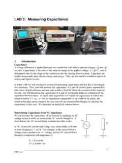
LAB 2: Measuring Capacitance
d32ogoqmya1dw8.cloudfront.netP443 L2 1 LAB 2: Measuring Capacitance 1. Introduction Capacitance A voltage difference V applied between two conductors will induce opposite charges +Q and –Q on each. Capacitance is the ratio of the induced charge to the applied voltage, C=Q/V, and is determined only by the shape of the conductors and the spacing between them.