Load And Resistance Factor Design
Found 6 free book(s)
Geotechnical - Load and Resistance Factor Design
www.in.govLoad & Resistance Factor Design: Deep Foundations (AASHTO 10.7 & 10.8) Piles Drilled Shafts Shallow Foundations (AASHTO 10.6) Spread Footings MSE Walls & Other Retaining Walls (AASHTO 11) Culverts, Tunnels and other buried Structures (AASHTO 11)
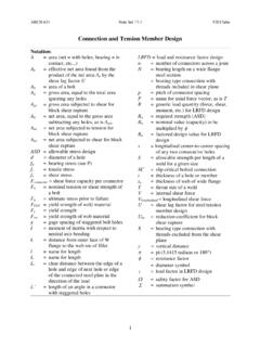
Connection and Tension Member Design
faculty-legacy.arch.tamu.eduLRFD = load and resistance factor design n = number of connectors across a joint N = bearing length on a wide flange steel section = bearing type connection with threads included in shear plane p = pitch of connector spacing P = name for axial force vector, as is T R = generic load quantity (force, shear, moment, etc.) for LRFD design R a

Lateral torsional buckling and slenderness
www.newsteelconstruction.com3. EUROCODE 3 DESIGN The lateral torsional buckling design guidance given in BSEN1993-1-1:2005 requires a reduction factor (c LT) to be applied to the moment resistance of the cross section to give the lateral torsional buckling moment resistance (M b,Rd). c LT is determined from a factor (F LT) and the non-dimensional slenderness factor (l LT
Chapter 12 SEISMIC DESIGN REQUIREMENTS FOR BUILDING …
www.ce.memphis.edudesign category and height limitations indicated in Table 12.2-1. The appropriate response modification coefficient, R, system overstrength factor, 0, and the deflection amplification factor, C d, indicated in Table 12.2-1 shall be used in determining the base shear, element design forces, and design story drift.

Chapter 7 Resistance and Powering of Ships
www.usna.edud. Increased Resistance in Shallow Water . 8. Read and interpret a ship resistance curve including humps and hollows . 9. State the importance of naval architecture modeling for the resistance on the ship's hull . 10. Define geometric and dynamic similarity . 11. Write the relationships for geometric scale factor in terms of length ratios, speed
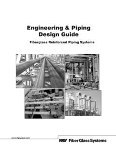
Engineering & Piping Design Guide - TS & M Supply
www.tsmfiberglass.com0.001 0.01 0.1 Pressure Loss - psig per 100 Feet of Pipe 10 11 01 00 1,000 10,0001 00,000 Flow Rate (gpm) - Gallons per Minute Fiberglass Pipe Pressure Loss Curves for Water