Load Dc Load
Found 9 free book(s)
Electronic Load Fundamentals - White Paper
www.altoo.dkWhen the load connects to a current source, its terminal voltage is equal to the imposed current multiplied by the programmed resistance value. Figure 7 depicts the I-V diagram of an electronic load in CR mode when loading a voltage or current source. A 5 Ω load on a 3 V voltage source will result in a 0.6 A sink current. Alternatively, the same
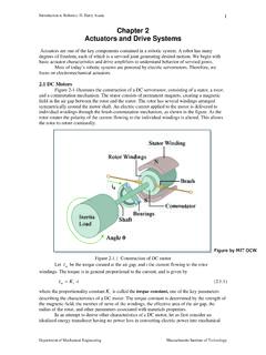
Chapter 2 Actuators and Drive Systems - MIT OpenCourseWare
ocw.mit.eduand needs a high torque to bear the load. In other words, the impedance of the actuator: m m m angular velocity torque Z ω τ = = (2.2.1) is much smaller than that of the load. τload ωload Joint Axis Gearing Arm Links DC Motor Figure 2.2.1 Joint axis drive system 1 Although a robotic system has multiple axes driven by multiple actuators ...

12ga Load Data Winchester Super Handicap Recipes
www.ballisticproducts.com12ga Load Data Winchester Super Handicap Recipes ® Super Handicap is the same propellant used in Winchester’s Super Handicap ammunition. This slow-burning, high energy propellant gives the shooter great handicap or long range sporting clays loads at up to 1250 fps with a 1-1/8 ounce shot charge. Great velocity with excellent patterns!

Lesson 14: Transfer Functions of Dc Motors
www.engr.siu.edu10/28/2015 5 EXAMPLE 14-1 SOLUTION (2) 9 x c) Find maximum back emf Answer d) Find no-load motor speed At no-load, T=0. Load torque is zero. T=0 TRANSFER FUNCTION OF ARMATURE- CONTROLLED DC MOTOR 10 x Write all variables as time functions

Geotechnical - Load and Resistance Factor Design
www.in.govLoad factor combinations to obtain resulting maximum force effects on the foundations are needed for limit states checks. This is done through structure modeling by varying the load factors over the specified range

ON Semiconductor Is Now
www.onsemi.comA DC/DC Resonant Converter Lr Cr Load Resonant Tank X1 X2 * * * T1 D1 D2 Cout Figure 7. A DC/DC Resonant Converter with Soft ZVS Switching Lr Cr Load Resonant Tank X1 X2 * * * T1 D1 D2 Cout L M To obtain DC voltage, output current of Figure 5 is rectified and stabilized by a large capacitance, providing a

Lesson 15: Induction Motor Testing: Lock-Rotor and No-load ...
www.engr.siu.eduExample 15-1: Following data is taken from no -load, locked rotor, and DC tests of a 3-phase, wye connected 40 HP, 60 Hz, 460 V, induction motor with a rated current of 57.8 A. The locked -rotor test is made at 15 Hz to minimize the errors due to saturation and skin effects. Determine the motor parameters and the total core,

Module 4: DC-DC Converters
nptel.ac.inThe principle of step down operation of DC-DC converter is explained using the circuit shown in Figure 3a. When the switch S 1 is closed for time duration T 1, the input voltage V in appears across the load. For the time duration T 2 is switch remains open and the voltage across the load is zero. The waveforms of the output voltage across the ...
LOAD FLOW STUDY IN POWER SYSTEM
ethesis.nitrkl.ac.inLoad bus: No generator is connected to the bus. At this bus the real and reactive power are specified.it is desired to find out the volatage magnitude and phase angle through load flow solutions.It is required to specify only Pd and Qd at such bus as at a load bus voltage can be allowed to vary within the permissible values.