Load Resistor Instructions
Found 10 free book(s)
Professional Thin Film Chip Resistors
www.vishay.comWhen the resistor dissipates power, a temperature rise above the ambient temperature occurs, dependent on the thermal ... different film temperatures and different achievable load-life stability (drift) of the resistance value. A suitable low thermal resistance of the ... set of instructions established for reproducibility. A
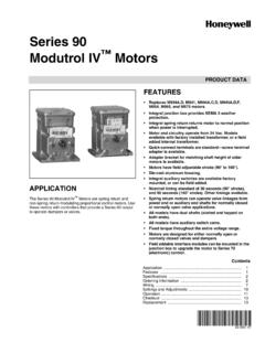
63-2631—07 - Series 90 Modutrol IV™ Motors
customer.honeywell.comDead Weight Load On Shaft: Power or Auxiliary End: 200 lb (90.8 kg) maximum. ... 221508A Resistor Board plugs onto Series 90 Motor quick-connect wire terminals. Provides same functionality as ... Check the ratings given in the instructions and on the product to make sure the product is suitable for your
MR-J2S- A Instruction Manual
dl.mitsubishielectric.cominstructions of both levels because they are important to personnel safety. ... servo motor and regenerative resistor on incombustible material. Installing them ... Install the servo amplifier in a load-bearing place in accordance with the Instruction Manual.

LM566C Voltage Controlled Oscillator
www.egr.msu.edunal resistor and capacitor. ... Frequency Stability vs Load Characteristics Square Wave Output TL/H/7854–4 Characteristics ... with instructions for use provided in the labeling, can effectiveness. be reasonably expected to result in a significant injury to the user.
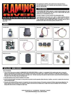
INSTALLATION INSTRUCTIONS PUSH BUTTON START SYSTEM
www.jegs.comload ratings (40 amps for the N.O. pin) are printed on the sides of the relays. The relays do not use internal diode or resistor snubbers. FOR ALL RELAYS: Pins 30 and 86 are connected to B+, 12VDC. Pin 85 is pulled low by the system to power the coil; pin 87 is the high current output which is enabled when the coil is powered. Pin 87A is not used.
BODY BUILDER INSTRUCTIONS - Mack Trucks
www.macktrucks.com•Wiring J1939”, page 52 • “9-pin Diagnostic Connector”, page 54 • “16-pin Diagnostic Connector”, page 55 • “Termination Resistor”, page 60 • “Parameter List”, page 61 • “Multiplexing Body Builder J1939 CAN ”, page 77 • “Support Inbound and Outbound J-1939 Message Information ”, page 85 CHU, CXU, GU, TD, MRU, LR USA139448393 Date 9.2017 Release 01 Page 2 (94)

MSD Digital 6A and 6AL Ignition Control 6A - PN 6201/62013 ...
documents.holley.comBallast Resistor: If your vehicle has a ballast resistor in-line with the coil wiring, it is recommended to bypass it. This wire is responsible for turning the MSD On and Off. Connects to a switched 12 volt source such as the ignition key or switch. (Max current draw of .250 mA.) This wire connects to the coil positive (+) terminal. This is the ...

PowerFlex 700 Adjustable Frequency AC Drive – Frames 0…6 ...
literature.rockwellautomation.comInternal Braking Resistor Code w/Resistor Y Yes NNo Not available for Frame 3 drives or larger. i Emission Code CE Filter § CM Choke A Yes Yes B # Yes No NNo No § Note: 600V class drives below 77 Amps (Frames 0-4) are declared to meet the Low Voltage Directive. It is the responsibility of the user to determine compliance to the EMC directive.
TROUBLESHOOTING TIPS FOR YOUR PERTRONIX IGNITOR …
www.pertronix.com.autroubleshooting tips for your pertronix ignitor® and coil installation first, read the instructions that came with your kit or coil! note: the pertronix ignitor is effectively a "go" or "no" system. this means that if the ignitor has a fault, it will not operate at all.. if the vehicle has an intermittent fault, at certain times or revs, this is generally an

PowerFlex 700 Adjustable Frequency AC Drive Installation ...
literature.rockwellautomation.comInstallation Instructions PowerFlex 700 Adjustable Frequency AC Drive – Frames 7…10 This document explains the 5 BASIC STEPS needed to install and perform a Basic Start-Up of the PowerFlex 700 AC drive. A Human Interface Module (HIM) is required to perform the Basic Start-Up routine covered in this manual.