Example: dental hygienist
INSTALLATION INSTRUCTIONS PUSH BUTTON START SYSTEM
load ratings (40 amps for the N.O. pin) are printed on the sides of the relays. The relays do not use internal diode or resistor snubbers. FOR ALL RELAYS: Pins 30 and 86 are connected to B+, 12VDC. Pin 85 is pulled low by the system to power the coil; pin 87 is the high current output which is enabled when the coil is powered. Pin 87A is not used.
Tags:
Information
Domain:
Source:
Link to this page:
Documents from same domain
Ford Installation Instructions - jegs.com
www.jegs.comMarch 21, 2006 Ford Performance Transmission Instructions 1 BD PERFORMANCE TRANSMISSION Ford Installation Instructions ... product returned prepaid with a complete service history and proof of purchase. A valid proof of purchase is a dated bill of sale. Repaired or replaced product will be returned to the customer freight collect.
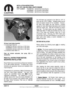
INSTALLATION INSTRUCTIONS 426 / 472 / 528 CID HEMI …
www.jegs.comThe Hemi Crate engines are assembled entirely from NEW Chrysler engineered components. The following is a list of potential issues which may arise during installation and the initial "fire up” process. If any problems arise, contact the Mopar Direct Connection Tech Line at 1-888-528
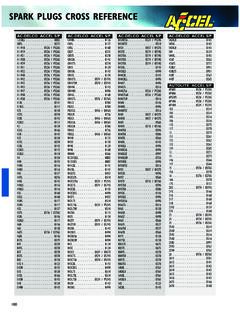
SPARK PLUGS CROSS REFERENCE - jegs.com
www.jegs.com1.This application listing is to be used as a guide only. Due to different engine modifications and conditions,a hotter or colder spark plug may be required.

HOLLEY SUPERCHARGER INSTALLATION …
www.jegs.comThe Ultra Charger Cam for big block Chevrolet has a slightly rough idle, acceptable vacuum for most street applications and outstanding mid and top range power.
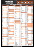
WHEEL NUT TORQUE SPECIFICATIONS (shown in ft. …
www.jegs.comLEXUS All Models Except: 2010-90 76 All Models Except: 2012 103 CT, ES, GS, IS, LS 2013 76-84 CT200h, ES350 2012-11 76 GS305 2013 76 GS350, GS450h, GS460 2011 76 HS250h, IS250, IS250c, IS350, IS350c, ISF 2012-11 76 IS250c, IS350c, ISF 2013 76 LS460, LS600h 2012-07 103 LINCOLN Continental 2002-90 85-105 LS 2006-00 100 …
PERFORMER RPM FE MANIFOLD CATALOG #7105 …
www.jegs.comA- Carburetor will work with non-EGR ... Remove dowel pins from end seal surface on Ford and Chrysler products. Use grip pliers for removal.
Holley 12-804 Fuel Pressure Regulator Installation ...
www.jegs.com2 PUMP MOUNTING AND INSTALLATION: The best location for mounting any electric fuel pump is the rear of the vehicle. The inlet and outlet of the pump must be
INTRODUCTION TABLE OF CONTENTS - jegs.com
www.jegs.com3 Edelbrock Performer Series Carburetor Owner’s Manual 8/94 METERING SYSTEMS The Edelbrock carburetor has three (3) basic systems that meter fuel to the engine: The Idle System, Primary Main System, and Secondary Main System.
HYFIRE IV SERIES OF ELECTRONIC IGNITION CONTROLS
www.jegs.comThe HYFIREfi IV Electronic Ignition Controls are designed to work with most original equipment ignition coils. For optimum performance use the Mallory PROMASTER fi Coil Part

Recommended Crate Engine Start-Up Procedure
www.jegs.comRecommended Crate Engine Start-Up Procedure 1. SAFETY FIRST! If the car is on the ground, be sure the emergency brake is set, the wheels are chocked, and the transmission cannot fall into gear.
Related documents

Professional Thin Film Chip Resistors
www.vishay.comWhen the resistor dissipates power, a temperature rise above the ambient temperature occurs, dependent on the thermal ... different film temperatures and different achievable load-life stability (drift) of the resistance value. A suitable low thermal resistance of the ... set of instructions established for reproducibility. A

63-2631—07 - Series 90 Modutrol IV™ Motors
customer.honeywell.comDead Weight Load On Shaft: Power or Auxiliary End: 200 lb (90.8 kg) maximum. ... 221508A Resistor Board plugs onto Series 90 Motor quick-connect wire terminals. Provides same functionality as ... Check the ratings given in the instructions and on the product to make sure the product is suitable for your
MR-J2S- A Instruction Manual
dl.mitsubishielectric.cominstructions of both levels because they are important to personnel safety. ... servo motor and regenerative resistor on incombustible material. Installing them ... Install the servo amplifier in a load-bearing place in accordance with the Instruction Manual.

LM566C Voltage Controlled Oscillator
www.egr.msu.edunal resistor and capacitor. ... Frequency Stability vs Load Characteristics Square Wave Output TL/H/7854–4 Characteristics ... with instructions for use provided in the labeling, can effectiveness. be reasonably expected to result in a significant injury to the user.
BODY BUILDER INSTRUCTIONS - Mack Trucks
www.macktrucks.com•Wiring J1939”, page 52 • “9-pin Diagnostic Connector”, page 54 • “16-pin Diagnostic Connector”, page 55 • “Termination Resistor”, page 60 • “Parameter List”, page 61 • “Multiplexing Body Builder J1939 CAN ”, page 77 • “Support Inbound and Outbound J-1939 Message Information ”, page 85 CHU, CXU, GU, TD, MRU, LR USA139448393 Date 9.2017 Release 01 Page 2 (94)

MSD Digital 6A and 6AL Ignition Control 6A - PN 6201/62013 ...
documents.holley.comBallast Resistor: If your vehicle has a ballast resistor in-line with the coil wiring, it is recommended to bypass it. This wire is responsible for turning the MSD On and Off. Connects to a switched 12 volt source such as the ignition key or switch. (Max current draw of .250 mA.) This wire connects to the coil positive (+) terminal. This is the ...

PowerFlex 700 Adjustable Frequency AC Drive – Frames 0…6 ...
literature.rockwellautomation.comInternal Braking Resistor Code w/Resistor Y Yes NNo Not available for Frame 3 drives or larger. i Emission Code CE Filter § CM Choke A Yes Yes B # Yes No NNo No § Note: 600V class drives below 77 Amps (Frames 0-4) are declared to meet the Low Voltage Directive. It is the responsibility of the user to determine compliance to the EMC directive.
TROUBLESHOOTING TIPS FOR YOUR PERTRONIX IGNITOR …
www.pertronix.com.autroubleshooting tips for your pertronix ignitor® and coil installation first, read the instructions that came with your kit or coil! note: the pertronix ignitor is effectively a "go" or "no" system. this means that if the ignitor has a fault, it will not operate at all.. if the vehicle has an intermittent fault, at certain times or revs, this is generally an

PowerFlex 700 Adjustable Frequency AC Drive Installation ...
literature.rockwellautomation.comInstallation Instructions PowerFlex 700 Adjustable Frequency AC Drive – Frames 7…10 This document explains the 5 BASIC STEPS needed to install and perform a Basic Start-Up of the PowerFlex 700 AC drive. A Human Interface Module (HIM) is required to perform the Basic Start-Up routine covered in this manual.