Transcription of HYFIRE IV SERIES OF ELECTRONIC IGNITION CONTROLS
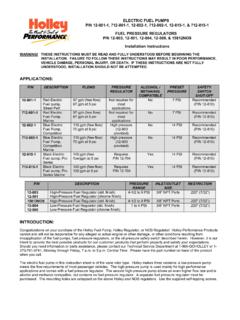
1 1 HYFIRE IV SERIES OF ELECTRONICIGNITION CONTROLSHYFIRE IVC IGNITION System Part No. 692, UniversalHYFIRE IVA IGNITION System Part No. 697, UniversalFor applications triggered by points, Mallory ELECTRONIC IGNITION Distributor (all models), original equipment electronicignition amplifiers and magnetic trigger pulses (magnetic pickup distributor or crank trigger IGNITION ). Optional adaptersare available for easy connection to early model Delco/GM HEI Systems, late model GM HEI/EST Systems, Ford TFIS ystems, and OEM magnetic pickup (non-computer; Ford DuraSpark, GM HEI and Mopar/Chrysler ELECTRONIC Systems).
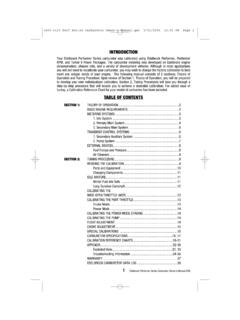
2 This product is legal to sell, distribute or install on vehicles in California. Executive Order : Mallory HYFIRE IV ELECTRONIC IGNITION CONTROLS are not compatible with distributorless systems or positiveground applications. The RPM Limiter in the HYFIRE IVC (Part No. 692) will not work properly with odd-fire or semi-even fire V6 Ballast Resistor/Loom Resistance IGNITION Bypass (Bypass Connector)..2 IGNITION Plug Plug RPM LimitersMallory PRO TACH I, IV and VI ..2 HYFIRE IVC IGNITION System 4 and 6 Cylinder to a Flat Surface Without Mounting to a Flat or Uneven SurfaceUsing Mounting to a Flat Surface with Shock Method using Adapters and HEI Systems/coil-in-cap with OEM module).
3 3-4 Late Model GM HEI/EST Systems (external coil).. 3-5 Ford TFI , 6 Ford DuraSpark Systems (non-computer type,without module).. 5-6 Early Model GM HEI Systems (non-computer type,without module)..6, 8 Mopar/Chrysler Corp. ELECTRONIC Systems(non-computer type, without module)..6, 9 Wiring Method Without Point , 9 Mallory ELECTRONIC IGNITION , UNILITE Distributors,Magnetic Breakerless Distributors or ElectronicAdvance Distributors (3-wire/red, brown, green)..7, 10 For OEM ELECTRONIC Systems with modules/amplifiers(Chrysler, Ford, and import)..7, 10 Magnetic Pickup Trigger Pulses (magneticpickup distributors or crank trigger IGNITION ).
4 7, 10 RPM Limiter Operation HYFIRE IVC IGNITION System(PN 692 only)..11 Optional IGNITION Template ..12 CONTENTSP arts included in this kit:1 HYFIRE IV ELECTRONIC IGNITION control - Part No. 692 or 6971 IGNITION control Harness - Part No. 293482 Terminal Connectors - Part No. 4501 Bypass Connector4 Cable Ties2 Spade Terminals8 Ring Terminals, 1/4"1 Ring Terminal, 3/8"5 Spade Receptacle Terminals4 Mounting Brackets4 #10 Sheet Metal ScrewsINSTALLATION INSTRUCTIONSFORM 1351 (REV. E) 10/992 GENERAL INFORMATIONThe HYFIRE IV IGNITION System Part Nos. 692 and 697 are not for marine RPM limiter in the HYFIRE IVC is not recommended as an engine speed governor.
5 Theuse of the RPM limiters is not recommended for applications equipped with a catalyticconverter. Similarly, forcing engine RPM past the RPM limiter continuously for long sustainedintervals can cause fuel build up in the exhaust system that may adversely affect yourapplication. The RPM limiting systems will not work properly with odd-fire V6 Ballast Resistor / Loom Resistance WireThe performance of the HYFIRE IV is not affected by the presence of the factory ignitionresistors or IGNITION ballast resistors in the wire from the IGNITION IGNITION Bypass (Bypass Connector)The Bypass Connector (supplied) fits into the IGNITION control Harness to convert back tostandard IGNITION .
6 If you use the Bypass Connector, use IGNITION ballast resistors designed foryour vehicle s distributor and coil (see diagrams for more information). This bypass methoddoes not work with magnetic pickup distributor or crank trigger IGNITION . Racing Applications: Itis not necessary to install IGNITION ballast resistors. However, do not use the Bypass Connectoruntil the IGNITION ballast resistors are installed in the wire from the IGNITION CoilsThe HYFIRE IV ELECTRONIC IGNITION CONTROLS are designed to work with most originalequipment IGNITION coils . For optimum performance use the Mallory PROMASTER Coil PartNo.
7 29440 (up to 7,500 RPM) or Part No. 29625 (up to 10,000 RPM).Fuel InjectionSome fuel injection systems need a voltage spike signal from the IGNITION coil before it willoperate properly. This signal changes once HYFIRE IV ELECTRONIC IGNITION CONTROLS areinstalled. The Mallory Fuel Injection and Tachometer Adapters Part Nos. 29074 and 29078supply the proper signal to the vehicle computer to operate the fuel injection procedure and diagrams are supplied with these Plug WiresYOU MUST USE suppression type (carbon core, spiral core, suppression core) spark plugwire. We recommend spiral core IGNITION wire, such as Mallory PRO SIDEWINDER IgnitionWire.
8 Suppression type spark plug wires prevent false triggering and possible prematureignition or accessory failures. DO NOT USE solid core (copper core; stainless steel core)spark plug wire with any ELECTRONIC IGNITION system or Plug GapsFor street applications, use your engine manufacturer's specifications. For racing applications,start with your engine manufacturer's specifications, then experiment with, and closely monitor,various gaps to achieve maximum WeldingUnplug the IGNITION control Harness from the HYFIRE IV ELECTRONIC IGNITION control andunplug any distributor harnesses (if possible) before any welding is done on the RPM LimitersMallory Proportional RPM Limiter Part Nos.
9 641-4, 641-6, 641-8, 642, 643 and 644 WILL NOTfunction with the HYFIRE IV ELECTRONIC IGNITION PRO TACH I, IV and VIThe RPM needle and shift light will work with the HYFIRE IV. However, the tach's proportionalcontroller that limits RPM WILL NOT function with the HYFIRE IV. Turn the LIMIT RPM knobslightly past 11,000 to prevent the limiter from interfering with the tach s other functions. SeeOptional IGNITION Accessories for more IVC IGNITION SYSTEM4 AND 6 CYLINDER OPERATIONThe HYFIRE IVC IGNITION System comes from the factory set for 8 cylinder engines. 4 or 6cylinder operations require you to set a switch inside the housing.
10 DO THIS BEFOREMOUNTING THE IGNITION BOX! Use a T-15 Torx tool to remove the four screws that holds the blank end panel to thehousing. Remove the blank end panel (see Figure 1). With the IGNITION upside-down, look inside and on the left side of the PC board you willsee a small two position switch. The switch (#1) nearest the end of the PC board is the 6cylinder switch. The other switch (#2) is the 4 cylinder switch. These switches are OFFfor 8 cylinder engines. Turn the appropriate switch ON for 4 or 6 cylinder operations. Attach the blank end panel to the PROCEDUREStep 1 Disconnect the battery ( ) cable to cut power to the system.