Transcription of MR4PMUHV Electronic Temperature/Defrost ... - Johnson …
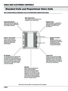
1 Product/TechnicalMR4 PMUHVI ssue DateJuly 25, 2002 2002 Johnson Controls, No. 24-8790-18, Rev. No. LIT-125190MR4 PMUHV ElectronicTemperature/Defrost control with Relay PackThe MR4 PMUHV Temperature/Defrost control withRelay Pack controls the temperature and defrostcycles on commercial refrigeration and freezerapplications. The control allows a hot gas or electricheat defrost cycle and uses time or temperature tocontrol defrost MR4 PMUHV Temperature/Defrost Controlincorporates temperature management, defrostmanagement, evaporator fan management, and alarmmanagement control functions. One convenientpackage consolidates the functions of a thermostat, adigital display, a timer, and a defrost 1: MR4 PMUHV ElectronicTemperature/Defrost control with Relay PackFeatures and BenefitsTSingle PackageProvides the functionality of multiple controlcomponents at a cost-effective Readable DisplayDisplays main sensor or auxiliary sensortemperatures; helps troubleshoot alarm , InterchangeableTemperature SensorProvides accurate control performance with up to300 feet (91 m) of sensor wiring.
2 (A temperatureoffset function may be set to accommodateapplications with longer sensor wire leads.)THeavy-Duty RelaysAllow direct control of compressors, fans, andheaters. Reduce installation MemoryRetains user-programmed settings in event ofpower ManagementFunctionsProvide alarm codes and a relay to eitheroperate a remote alarm or trigger a MR4 PMUHV Electronic Temperature/Defrost control with Relay Pack Product/Technical BulletinFederal Communications Commission(FCC) Compliance StatementThis equipment has been tested and found tocomply with the limits for a Class A digital devicepursuant to Part 15 of the FCC Rules. These limitsare designed to provide reasonable protectionagainst harmful interference when the equipment isoperated in a commercial environment. Thisequipment generates, uses, and can radiate radiofrequency energy and, if not installed and used inaccordance with the instruction manual, may causeharmful interference to radio of this equipment in a residential area islikely to cause harmful interference, in which casethe user is required to correct the interference athis/her own Compliance StatementThis digital apparatus does not exceed the Class Alimits for radio noise emissions from digitalapparatus set out in the Radio InterferenceRegulations of the Canadian Department.
3 The MR4 PMUHVT emperature/Defrost control is intended to controlequipment under normal operating failure or malfunction of theMR4 PMUHV control could lead to an abnormaloperating condition that could cause personalinjury or damage to the equipment or otherproperty, other devices (limit or safety controls) orsystems (alarm or supervisory systems) intendedto warn of, or protect against, failure or malfunctionof the MR4 PMUHV control must be incorporatedinto and maintained as part of the control MR4 PMUHV Temperature/Defrost Controlconsolidates the functions of a temperature control ,a digital temperature readout, a defrost cycle timer,and a defrost termination MR4 PMUHV control provides direct control inmany refrigeration applications. See electricalratings in Tables 6 through 8 for more MR4 PMUHV control performs the followingfunctions:Temperature ManagementSeveral settings define the temperature controlfunctions: Setpoint and Differential settings establish thecontrolled temperature and acceptable temperaturerange.
4 Cycle Delay establishes a set time interval betweencompressor restarts to avoid excessive cycling. Deep Freeze Time establishes the duration of amanually-initiated freeze cycle. Sensor Failure Operation initiates a predefinedresponse to a temperature sensor ManagementSeveral settings define the control functions for alarms: High and Low Temperature Alarms providenotification of temperatures that exceeduser-designated high and low limits. Alarm Time Delay keeps short-durationtemperature changes from triggering an alarm. Alarm Differential keeps the alarm from cyclingrapidly on and off due to minor temperaturefluctuations. Alarm Codes assist in Cycle ManagementThe MR4 PMUHV Temperature/Defrost control allows ahot gas or electric heat defrost cycle, and uses time ortemperature to control defrost Fan ManagementThese settings define the control functions forevaporator fans: Fan Operating Mode controls whether evaporatorfans run continuously or only when the compressoris on.
5 Fan Start-Up Delay follows either time-based orevaporator-temperature-based startup after a timed-defrost application, a properly-wiredreversible fan motor can run in reverse, bringingwarm air over the evaporator Electronic Temperature/Defrost control with Relay Pack Product/Technical Bulletin 3 Binary Input ResponseBinary Input Function allows the user to selectwhich output relays respond to a binary input(switch) if the binary input contacts are open for atime (in minutes) longer than the Binary Input FeaturesThe MR4 PMUHV control uses several other settingsto control specific features: Keyboard locking disables/enables change ofthe setpoint and other functions, reducingaccidental or unauthorized changes of thecontrol settings. Self-Test Procedure initiates a test cycle of alloutputs and tests all Light-Emitting Diodes(LEDs).
6 See Initiating a Manual Self-Test. Manual Deep Freeze Cycle manually initiates adeep freeze cycle, which is useful when loadinga cold room or a display cabinet. See Initiating aManual Deep Freeze Cycle. Manual Defrost interrupts normal controloperation and initiates an immediate defrostcycle. See Initiating a Manual Defrost additional information about control functionsand how to program them, see Programming theControl and control Module Front PanelThe control module has an LED display and buttonsfor entering programming information and activatingvarious display has three LED digits. It displays atemperature range from -40 to 176 F (-40 to 80 C)in increments of 1F or C . The display also featuresthree status FanStatus LEDD efrost Status LEDC ompressor OutputStatus LEDUpButtonDownButtonFigure 2: control Module Front PanelInstallationSee Mounting and Wiring for installation (92)2-3/8(61)7-15/16(202)1-3/4(44)1-5/8( 42)6(152)3(76)Figure 3: Relay Pack with Mounting BracketDimensions, in.
7 (mm)2-5/16(58)2-3/4(70)3(75)1-3/8(35)1-1 /8(28)2-11/16(68)Figure 4: control Module Dimensions, in. (mm)1/4(6)2(50)78-3/4(2000)Figure 5: A99BB-200C Sensor Dimensions, in. (mm)4 MR4 PMUHV Electronic Temperature/Defrost control with Relay Pack Product/Technical BulletinMountingThe MR4 PMUHV control is not position the MR4 PMUHV control as a single unit, orseparate the control module and relay pack andmount them individually to allow convenient wiringand the MR4 PMUHV control as aSingle UnitBefore mounting the relay pack, ensure that there issufficient space. Follow these steps to mount therelay pack:1. Hold the MR4 PMUHV control against thesurface and use it as a template to trace themounting Drill holes for mounting screws in the Use three screws (No. 8 or No. 10 size) tomount the MR4 PMUHV the control Module and RelayPack SeparatelyMount the relay pack and the control module within18 in.
8 (46 cm) of each the control Module from theRelay PackFollow the steps to separate the control module andthe relay pack. See Figures Locate the mounting clip that holds the controlmodule to the mounting bracket on the Squeeze the forward portion of the mounting cliptogether and slide the mounting clip back toremove the mounting clip from the back of thecontrol Pull the control module out of the mountingbracket on the relay Disconnect the wiring from the control moduleand the relay pack terminals V1, V2, O1, andO2. See Figures the Relay PackBefore mounting the relay pack, ensure that there issufficient space. Follow these steps to mount therelay Hold the relay pack with mounting bracketagainst the surface and use as a template totrace the mounting Drill holes for mounting screws in the slots Use three screws (No.)
9 8 or No. 10 size) to mount therelay the control ModuleBefore mounting the control module, ensure that there issufficient free space [at least 2-3/4 inches (70 mm)]behind the mounting surface. Follow these steps tomount the control Cut a hole 1-3/16 x 2-13/16 inches (29 x 71 mm).2. Remove the retaining clip from the control Insert the control module into the Install the retaining clip and slide forward to adjustfor Reconnect the wires on the terminals in the relaypack to the corresponding terminals on the controlmodule. See Figures ClipControlModuleMounting BracketRelayPackFigure 6: Removing the Mounting Clip andControl ModuleV2V1O1O2 Figure 7: Relay Pack Terminal Positions on CircuitBoardMR4 PMUHV Electronic Temperature/Defrost control with Relay Pack Product/Technical Bulletin 5 Wiring!
10 WARNING: Risk of Electric avoid electric shock or damage to equipment,disconnect all power supplies before wiring anyconnections. More than one disconnect may benecessary to completely de-energize Sensors and Binary InputWire the sensors and binary input (if used) as shownin Figures 8-9. The Sensor (S1 or S2) and SensorCommon (SC) wires are interchangeable whenusing the A99B temperature sensors. The binaryinput shares a common terminal with the to ControlEvaporator Te m p e r a t u r eSensorBinaryInput (Switch)Main Te m p e r a t u r eSensorSensorCommon12 VACO1O1O2O2 Note: Black boxes indicate unused 8: Wiring the control ModuleLoosen screw to open terminal; tighten screw to secure wiring : Black boxes indicate unused 9: Rear View of the control ModuleUse Temperature Sensor Offset to compensate forsensor leads longer than 300 ft (if F is used) or165 m (if C is used).