Load Switch
Found 11 free book(s)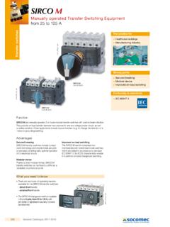
SIRCO M - Socomec
www.socomec.comImproved on-load switching The SIRCO M switch comprises two mechanically interlocked load break switches which are tested in accordance to standard IEC 60947-3. Its AC23 characteristics enable it to perform on-load changeover switching. > Healthcare buildings > Manufacturing industry The solution for > Secured breaking > Modular device

Control and Load Switch Specifications - Rockwell …
literature.rockwellautomation.com4 Rockwell Automation Publication 194-TD002B-EN-P 194E Load Switches Specifications Performance Data 16 A 25 A 32 A 40 A 63 A 80 A 100 A Aux. UL/CSA Applications Contacts Continuous current [A]162532406380 100 —
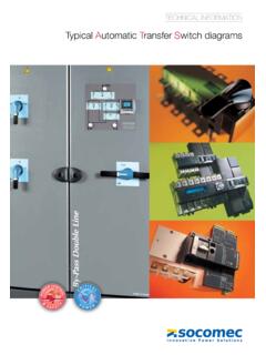
Typical Automatic Transfer Switch diagrams - Socomec
www.socomec.com• Load shedding principle diagram: ATyS p associated to an Input/Output Module can deliver a signal to the motorised switch in order to realise the load shedding. UPS 230Vac + Critical loads Non critical loads • Emergency stop on ATyS • Secured disconnection integrated for load isolation thanks to a double switching technology per pole ...

Control4® Wireless Switch
www.control4.comControl4® Wireless Switch The Control4® Wireless Switch provides on/off control for a variety of load types. With its robust relay and high amperage rating, the Switch can handle even high in-rush loads such as fountain pumps or large banks of fluorescent lights. It can even be used to switch wall outlets.

UNDERSTANDING RELAYS - Autoshop 101
autoshop101.comThe control circuit has a small control coil while the load circuit has a switch. The coil controls the operation of the switch. RELAY ENERGIZED (ON) Current flowing through the control circuit coil (pins 1 and 3) creates a small magnetic field which causes the switch to close, pins 2 and 4. The switch, which is part of the load circuit,

Electrical Design Standard Symbols - Red-Bag
www.red-bag.comoff load 07-13-08 switch-disconnector on load 07-21-08 fuse-disconnectoe off load 07-21-09 fuse switch-disconnector on load 07-14-04 voltage indicator capacitive . id. no. issue 8 sheet 5 of 40 doc.no. bn-ds-e2 symbol for key diagram, m.v. and l.v. …

Aruba 5400R ZL2 Switch Series - Data sheet
www.arubanetworks.comswitch from two switches; servers or switches can be attached using standard LACP for automatic load balancing and high availability; simplify network operation by reduce the need for complex protocols like Spanning Tree Protocol (STP), Equal-Cost Multipath (ECMP), and VRRP (requires v3 modules)

Topologies for switch mode power supplies - …
www.st.comswitch. III - 1.2 Off line forward regulators The forward converter transfers directly the energy from the input source to the load during the on-time of the power switch. During off-time of the power switch, the energy is freewheeling through the output inductor and the rectifier D 2, like in a chopper (see figure 1). 2P out ηV inmin (1 + A + A2)

Aruba CX 8325 Switch Series Data Sheet
www.arubanetworks.comRedundant and load-sharing fans and power supplies • Increases total performance and power availability while providing hitless, stateful failover Hot swappable power supply and fan modules • Allows replacement of accessories modules without any operational impact on other modules nor the switch operations Separate data and control paths

Inspection and Testing of Emergency Generators
www.health.state.mn.usswitch(es) on the automatic transfer switch(es) or by opening a normal breaker [see NFPA 110(10), Sec. 8.4.3]. Opening a normal breaker shall not be required. 3) Load tests must include complete cold starts [see NFPA 99(12), Sec. 6.4.4.1.1.4(B); NFPA 110(10), Sec. 8.4.4 ].
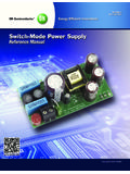
Switch - ON Semiconductor
www.onsemi.comwithin the core of the inductor. When the power switch is turned off, the core contains enough energy to supply the load during the following off period plus some reserve energy. When the power switch turns off, the voltage on the input side of the inductor tries to fly below ground, but is clamped when the catch diode D becomes forward biased.