Low voltage motor
Found 11 free book(s)
Reference Guide Low Voltage Motors Basics of IEC Motors
esrmotors.comLow Voltage Motors Basics of IEC Motors. 2 BASICS OF IEC REFERENCE GUIDE - Basics of IEC Motors ABB As North American manufacturers increase export ... is what we’d call a subfractional motor, while NEMA’s 56 frame is our most common, covering about 1/4 to 1-1/2 HP.
MNS-MCC Low Voltage Motor Control Center Application …
library.e.abb.commanufacturing and application of Low Voltage Motor Control across the entire range of industrial and utility installations. To achieve the greatest possible flexibility, the MNS-MCC Motor Control Center offers plug-in, withdrawable, and full height unit technology, with up to 4000A horizontal and 1600A vertical bus.

Low voltage motors Installation, operation, maintenance ...
library.e.abb.com3. Some special motor applications may require additional instructions (e.g. when supplied by frequency converter). 4. Observe rotating parts of the motor. 5. Do not open terminal boxes while energized. Low voltage motors manual, 3GZF500730-85 Rev. G 07-2016 | ABB Motors and Generators 5
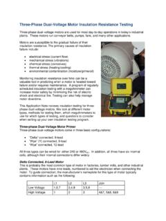
Three-Phase Dual-Voltage Motor Insulation Resistance …
www.aemc.comLow Voltage 1,7 2,8 3,9 4&5&6 High Voltage 1 2 3 4&7, 5&8, 6&9 In this case, high-voltage connections are the same as for delta motors. The wiring diagram for a wye connected 9-lead motor is as follows: Wye connected 9-lead wiring diagram Note that the wye-connected 9-lead motor’s internal connections vary from the delta motor.
Baldor Motor Basics: Power Systems and Voltage
www.powertransmission.comstable so that the limit of the motor’s low-voltage capability is seldom tested. On motors larger than 10 HP the 200-volt motor is general-ly the best choice; but in many situations 230-volt motors are frequently and successfully applied on the 208-volt systems. In some cases a derate table is provided for the “low-voltage” situation.
Standard Voltage Ranges and Ratings - Powell Ind
www.powellind.comTherefore, the 508V will appear on the nameplate of the low voltage power circuit breaker as the maximum voltage. The motor control center will list the system voltage of 480V. The motors connected to the motor control center will list the utilization voltage of 460V.
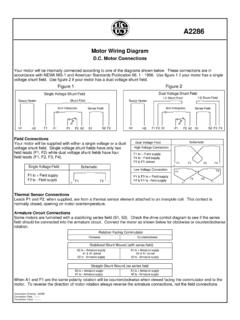
D.C. Motor Connections Figure 1 Figure 2
apps.motorboss.comMotor Wiring Diagram D.C. Motor Connections Your motor will be internally connected according to one of the diagrams shown below. These connections are in accordance with NEMA MG-1 and American Standards Publication 06. 1 - 1956. Use figure 1 if your motor has a single voltage shunt field. Use figure 2 if your motor has a dual voltage shunt field.
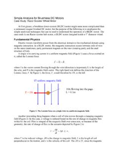
Simple Analysis for Brushless DC Motors Case Study: Razor ...
web.mit.eduThe Lorentz force law shows that a motor can produce force from current. The flux/voltage relationship shows that it can produce voltage from velocity. (If you spin a motor externally, it can act as a generator.) The key, though, is that the motor is always doing both of these at the same time. A stationary wire produces zero power, no matter ...

MP-Series Low-inertia Servo Motor with 100 mm to 165 mm ...
literature.rockwellautomation.comMP-Series Low-inertia Servo Motor with 100 mm to 165 mm Frame Size Prolonging Motor Life Proper design and maintenance can increase the life of a servo motor. Follow these guidelines to maximize the life of a servo motor within your environment: • Always provide a drip loop in each cable to carry liquids away from the connection to the motor.
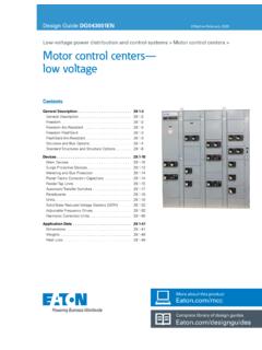
Motor control centers— low voltage - Eaton
www.eaton.comwritten for low-voltage motor control centers, unlike C37.20.7 that is a guideline for testing metal-enclosed switchgear up to 38 kV. Eaton’s Freedom Arc-Resistant motor control center is tested in accordance with CSA C22.2 No. 0.22-11 titled “Evalua tion methods for arc resistant ratings of enclosed electrical equipment”.

NCP5183 - High Voltage High Current High and Low Side …
www.onsemi.comLow Level Output Voltage IDRVL = 0 A VDRVLL 35 mV Low Level Output Voltage (HS Driver) IDRVH = 0 A VDRVHL 35 mV High Level Output Voltage IDRVL = 0 A, VDRVLH = VCC − VDRVL VDRVLH 35 mV High Level Output Voltage (HS Driver) IDRVH = 0 A, VDRVHH = VB – VDRVH VDRVHH 35 mV Output Positive Peak current VDRVL = 0 V, PW = 10 s IDRVLH 4.3 A