Penetration Welds
Found 10 free book(s)
WELDS- STATIC AND FATIGUE STRENGTH – II
www.steel-insdag.orgPartial penetration welds, shown in Fig. 3, differ in two ways from the full penetration welds: the reduction in cross section and the uncertainty of the weld root quality. Firstly, there is a reduction in the cross section at the joint resulting in overloading and severe

2. Design of Welded Connections 2.1 Stresses
app.aws.orgweld size for flare groove welds when fi lled flush to the surface of a round bar, a 90 O bend in a formed section, or a rectangular tube shall be as shown in Table 2.1 . 2.3.4 Complete Joint Penetration Groove Welds. 2.3.4.1 Weld Size. The weld size of complete joint penetration groove welds shall be the thickness of the thinner part joined.

Blueprint Reading Esstentials in Welding
spot.pcc.edu• Depth of penetration • Height of reinforcement • Groove type • Groove dimensions • Location, process • Filler metal • Strength, number of welds • Weld shape • Surface finishing. All this information would normally be included on the welding assembly drawings. Indicating Types of Welds
2. Design of Welded Connections - American Welding Society
app.aws.orgpenetration groove welds, the required weld size, as de-fined in this code. Shop or working drawings shall spec-ify the groove depths (S) applicable for the weld size (E) required for the welding process and position of welding to be used. 2.2.4 Groove Welds. Detail drawings shall clearly indi-cate by welding symbols or sketches the details of

Structural Steel Connections, Joints Details
www.nrc.govComplete and Partial Penetration Groove Welds BMA Engineering, Inc. – 6000 6 Types of Groove Welds BMA Engineering, Inc. – 6000 7 Plug or Slot Weld BMA Engineering, Inc. – 6000 8. Stitch or Skip Weld BMA Engineering, Inc. – 6000 9 Basic of Welding • Structural welding is a process whereby the parts to be ...
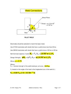
Weld Connections - OAL
people.tamu.eduFig 2: Partial penetration groove welds . Title: Microsoft Word - WeldREV Author: Sahar Haque Created Date: 7/27/2012 6:07:11 AM ...

Joint Design & Welding Symbols - CWB Group
www.cwbgroup.orgEdge Welds. FIG. 9. Edge welds. Download edge welds in 3D to your phone. Reference. An edge weld is a weld in an edge . joint, a flanged butt joint or a flanged corner joint, in which the full thick-ness of the members are fused. They are neither groove welds or fillet welds and they are not surfacing welds because these welds are form-
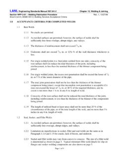
1.0 ACCEPTANCE CRITERIA FOR COMPLETED WELDS
engstandards.lanl.gov1.2 Socket and Fillet Welds 1.2.1 As-welded surfaces are permitted; however, the surface of welds shall be sufficiently free from coarse ripples, grooves, overlaps, abrupt ridges, undercut, and valleys. 1.2.2 The surface condition of the finished welds shall be suitable for the proper interpretation of nondestructive examinations.
1.0 ACCEPTANCE CRITERIA FOR COMPLETED WELDS
engstandards.lanl.gov1.2 Seal, Socket, and Fillet Welds 1.2.1 As-welded surfaces are permitted; however, the surface of welds shall be sufficiently free overlaps, abrupt ridges, and valleys. 1.2.2 Limitation on imperfections in socket, fillet and seal welds are the same as in Paragraph 1.1.4 and 1.19 for cracks, lack of fusion, and undercut.

API Standard 1104
www.api.orgwelds throug ved welding p rd covers the welds in carbo compression, leum, petroleu ogen, and wh systems. It ap ce welding. Th tal arc weldin c welding, gas, plasma arc w elding proces sing a manua c welding tech The welds ma y a combinat rd also presen nalysis of we hnicians and It covers the rticle, liquid p e acceptance elds tested t c ...