Resistor Calculation
Found 9 free book(s)
I2C Bus Pull-Up Resistor Calculation
e2e.ti.comI2C Bus Pullup Resistor Calculation Application Report SLVA689–February 2015 I2C Bus Pullup Resistor Calculation RajanArora ABSTRACT Pullup resistor calculation for I2C interface is a commonly asked question. In this application note we show how to use simple equations for this calculation. Contents

PowerFlex Dynamic Braking Resistor Calculator
literature.rockwellautomation.comResistor to the DC bus and dissipating power, or isolating the resistor from the DC bus. The most important rating is the collector current rating of the Chopper ... Maximum Power Calculation Voltage 208 375V DC 395V DC 240 375V DC 395V DC 400 750V DC 790V DC 480 750V DC 790V DC 575 937.5V DC 987V DC 600 937.5V DC 987V DC 600 (Frame 5 and 6 ...
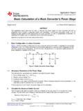
Basic Calculation of a Buck Converter's Power Stage (Rev. B)
www.ti.comThis adds less than 1% inaccuracy to the voltage measurement and for the calculation of the feedback divider, the current into the feedback pin can be neglected. The current also can be a lot higher. The only disadvantage of smaller resistor values is a higher power loss in the resistive divider, but the accuracy is increased a little.
12. Transformers, Impedance Matching and Maximum Power ...
www.hunter.cuny.eduThe calculation of equation (3) and (4) follows as before. Mostly the transformers we use have the same kind of wire for the primary and secondary. In ... resistor something like R=5,000 ohms to the secondary and measure the voltage across the load. Use equation (4) to calculate the secondary voltage. ...

Choosing an Appropriate Pull-up/Pull-down Resistor for ...
www.ti.comThis calculation results in a minimum value because choosing any value lower for RPull-up causes a higher current than the test condition current to flow in Q1. If a current higher than the test condition current flows through Q1, the voltage drop across Q1 is higher and no longer ensured. The results of Equation 4 and

RESISTOR COLOR CODE GUIDE - University of California, San ...
neurophysics.ucsd.eduThe resistor value is read from the left to right. If there is no tolerance band, then find the side that has a band closest to a lead and make that the first band. Resistor Lead Left Right 254 Ω 1 %+-1.0 KΩ 5%+-Red Black Yellow Silver Page 1 200 KΩ 10 %+-+- 1 % 1st 2nd 3rd 4th 1st 2nd 3rd 4th 5th Calculation

AN5028 Application note - STMicroelectronics
www.st.compower losses calculation DocID030470 Rev 1 9/20 . 2 Turn-off power losses calculation . The power losses calculation can be helpful for designers to: Estimate the total power losses generated inside a diode, in order to evaluate its junction temperature. Estimate the total power losses generated by different diodes (in snubber circuits,
Experiment 8: Capacitance and the Oscilloscope
www.columbia.edu2. Resistor: it causes a drop in the voltage due to microscopic collisions between the flowing charges and the atoms of the material or interactions with EM potential. Its macroscopic quantity is the resistance ( R) 3. Capacitor: it is composed by two conductors (e.g. plates) separated by a non-conducting material.
AN2867 Application note - STMicroelectronics
www.st.comOctober 2021 AN2867 Rev 15 1/59 1 AN2867 Application note Oscillator design guide for STM8AF/AL/S, STM32 MCUs and MPUs Introduction Many designers know oscillators based on Pierce-Gate topology (hereinafter referred to as