Swr Series
Found 9 free book(s)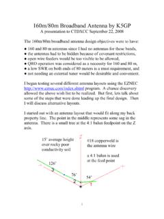
160m/80m Broadband Antenna by K5GP
www.ctdxcc.orgThe SWR plot for an 80 meter broadband dipole is shown below. For the antenna layout below, the center capacitor is 15 pF at element 3 between elements 2 and 4 and a 4:1 balun feeds the antenna between elements 1 and 2. The SWR is less than 1.7 to 1 across the entire 80 meter band. How do we get back the 160 meter resonance? By placing a series
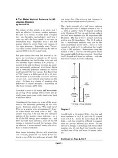
A Ten Meter Vertical Antenna for All License Classes
www.qsl.nettuning the analyzer… I found a dip in SWR reading at 24 MHz. Note: This method works like the Grid Dip Oscillator of vacuum tube days of past. I found that if I reduced the value of C… then the frequency would go upwards. I connected the two variable capacitors in series to lower the C value. By adjusting the two caps while

Homebrew HF SWR/Power Meter - na0tc.org
www.na0tc.orgMay 04, 2012 · •The lead inductance and C2 result in a series resonance that progressively deteriorates bridge balance as the frequency is raised Common Sensors 5/4/2012. ... SWR LED Radio Shack 276-0017 100K Forward 100K + 10K-3 1.21M 10 9 8 1 uF 1.0 uF Latch Relay1 +12 VDC 100 17 mA 1 16 +-Latch Relay1 13 8 6 9 4 11 0.1 uF To SWR Shutdown 5.1K Reset To +8 ...

Understanding SWR by Example - ARRL
www.arrl.orgas a 50 Ω resistor with a 100 nH inductor in series, or perhaps some capacitance to ground. In this situation, the SWR is not 1:1 because of the reactance. Even antennas that show a perfect 1:1 SWR in mid-band will typically have some larger SWR at the band edges, often due to the reactance of the antenna changing with frequency.

Antenna Impedance Matching – Simplified
abracon.comStanding wave ratio (SWR) is a measure that defines how well the antenna impedance is matched to the connected Tx line impedance. A value less than 1.5 is desirable. A low flat SWR enables maximum power transfer from the ... When a series inductor is connected to the antenna, the combined impedance of the antenna ...
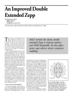
An Improved Double Extended Zepp - Antennas By N6LF
rudys.typepad.comThe series capacitors are 17 pF, and since he isn’t interested in CW, Dick adjusted the length for the lowest SWR at the high end of the band. The antenna could have been tuned somewhat lower in frequency and would then provide an SWR < 2:1 over the entire band, as indicated by the dashed line in Fig 8. This antenna provides wide bandwidth
My Loop Antenna - RCARC
www.rcarc.orgAntenna Dimension Counterpoise Band 2:1 SWR BW Rad. Res. ΩΩΩΩ Loss Res. Efficiency Base-loaded vertical (AB2EW) 6.67' tall Single wire, 25' long, on ground 40m 185 kHz 0.863 65.3 Ω 1.3% 30m 410 kHz 1.78 69.3 Ω 2.5% Base-loaded vertical (AB2EW) 15' tall Single wire, λ /4 long, elevated 5' 40m 248 kHz 4.68 32.1 Ω 12.7%

Ferrite and Common Mode Chokes - W4CAE
w4cae.comget a decent SWR match. You can also sometimes see this effect when using an external (to your radio) SWR bridge. SWR should be the same along the entire feed line. If the external meter shows one SWR and your radio’s built in meter shows another then you might have a common mode current problem.

AA-2000 ZOOM RigExpert
www.rigexpert.comThe analyzer is designed for measuring SWR (standing wave ratio), return loss, cable loss, as well as other parameters of cable and antenna systems in the range of 100 kHz to 2000 MHz. A built-in ZOOM capability makes graphical measurements especially effective. An integrated Time Domain Reflectometer