Transformer design
Found 6 free book(s)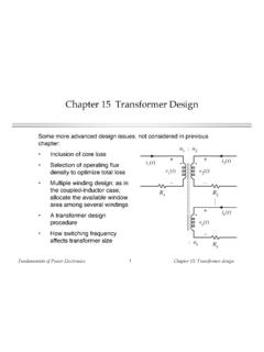
Chapter 15 Transformer Design
ecee.colorado.eduFundamentals of Power Electronics Chapter 15: Transformer design3 15.1 Transformer Design: Basic Constraints Core loss Typical value of for ferrite materials: 2.6 or 2.7 B is the peak value of the ac component of B(t), i.e., the peak ac flux density So increasing B causes core loss to increase rapidly This is the first constraint P fe = K fe ...

Power Transformer Fundamentals: Design and Manufacturing
r5.ieee.orgPower Transformer Fundamentals: Design and Manufacturing Waldemar Ziomek, Engineering Manager CG Power Systems Canada Inc IEEE Training, Houston, Texas, Oct.8-9, 2013 Overview •Transformer Design –Transformer Types –Construction and Parts •Core & Coils –Electrical design •Losses & Impedance •Thermal, Dielectric & Short Circuit

ELECTRICAL CONNECTION DIAGRAMS ACME …
www.ideadigitalcontent.comGENERAL ELECTRICAL CONNECTION DIAGRAMS 122 ACME ELECTRIC U MILWAUKEE, WI U 00..1 U acmetransformer.com GENERAL ACME® TRANSFORMER™ DESIGN FIGURES Design Figures Sections I, II, III & IV Design A Design B Design E Design H Design C Design D Design F Design G Design I These drawings are for reference only.

Power Transformer Factory Test using IEEE Standards
r5.ieee.org9/24/2013 2 Power transformer testing Objective of testing •Compliance to applicable standards •Compliance to customer specification •Verify guaranteed parameters •Assess quality and reliability •Verify design •Obtain additional performance and reference data 3 4Power transformer testing Classification of tests
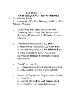
LECTURE 34 HIGH FREQUENCY TRANSFORMER
www.engr.colostate.edutransformer to take up a volume consistent with their expected power dissipation. What is not intuitively clear is that there is an optimum core flux density, B OPT, where the total of copper and core losses will be a minimum. This B OPT will guide transformer and AC inductor design. For if we hit the B OPT target we will operate with minimum
LLC Converter Design Note - Mouser Electronics
www.mouser.comLLC Converter Design 6 Design Note AN 2013-03 V1.0 March. 2013 3.1 Converter gain The winding ratio between the primary winding, n pri, and the secondary winding, n sec, gives one gain-term as in other transformer isolated SMSP: pri XFMR n n G sec (1)