Understanding Time Current Curves
Found 7 free book(s)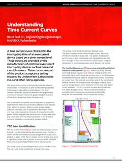
Understanding Time Current Curves - Maverick Technologies
www.mavtechglobal.comWHITE PAPER UNDERSTANDING TIME CURRENT CURVES 4/6 The next section of the curve moving up the time axis is the long time section. Long time settings cover the time range from 0.5 to 1000 seconds. The purpose of long time settings is to allow a time-based delay to elapse before tripping the circuit breaker for low level current faults.
Understanding Trip Curves - c3controls
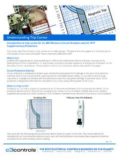
img.c3controls.comTrip curves plot the interrupting time of overcurrent devices based on a given current level. They are provided by the manufacturers of circuit protection devices to assist users with selecting devices that provide proper equipment protection and performance, while avoiding nuisance tripping. Tells you how this behaves. Understanding Trip Curves

Understanding The IEC Based IDMT Settings of Phase Over ...
pangonilo.cominverse curves at various TMS, which ranges from 0.1 to1. By varying the α and K values in the same formula, four standard curves, the normal inverse, very inverse, extremely inverse and the long-time inverse are available. Introduction Phase over-current protection is a common and widely used protection scheme that is implemented in high voltage

The Secret to Understanding Arc Flash Calculations
assets.informa.comtime, short time, and instantaneous. The equations in the Table have one unknown: I bf. When the incident energy is known, the HRC can be determined from the information in Table 2. Notes: I bf is based on a working distance of 455 mm (18 in.). I bf is between 700A and 106,000A. TCC curves are not necessary when I bf is in the range above.
Understanding Insulation Resistance Testing - AEMC
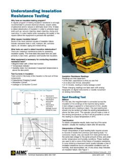
www.aemc.comthe differences in readings (see curves, Figure 2). Tests by this method are sometimes referred to as absorption tests. Good insulation shows a continual increase in resistance (see curve D) over a period of time (in the order of 5 to 10 minutes). This is caused by the absorption; good insulation shows this charge effect over a time period much

UNDERSTANDING SCR POWER CONTROLS
www.avatarinstruments.comtime base. The superior firing resolution and speed of response of the A1Z SCR is instantly apparent. Avatar Instruments A1Z SCR 50% output with variable time base zero voltage switching. To show the full effect, the scope had to be set on a 500ms scale (right hand), or a 5X longer time base than the 100ms screen above on the left.

Understanding Design, Operating, and Posted Speed
static.tti.tamu.eduDesign Speed and Horizontal Curves Background: As Figure 3 shows, horizontal curves are circular arcs-i.e., a curve to the left or right-that connect straight sections of highway. On a horizontal curve, the design speed is used to determine acceptable ranges for the sharpness of curvature and how much the pavement surface is banked