Voltmeter
Found 8 free book(s)
UNDERSTANDING RELAYS - Autoshop 101
autoshop101.comA voltmeter can be substituted in place of a test light; however be aware if the contacts are partially burned, the voltmeter will show voltage indicating good contact even when bad. Remember high impedance digital voltmeters draw almost no current.

Intro to Electricity - Home | NYU Tandon School of Engineering
engineering.nyu.edu• A voltmeter measures the potential difference (voltage) between two points • An ohmmeter measures resistance • A multimeter combines these functions, and possibly some additional ones as well, into a single instrument. Digital Multimeter 2 • Voltmeter – Parallel connection
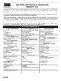
CDL PRE-TRIP VEHICLE INSPECTION MEMORY AID - Oregon
www.oregon.govAmmeter/Voltmeter : Springs &/or Air Bags . Brakes . Mirrors . Spring/Air Mounts and U-Bolts ; Slack Adjusters and Pushrods Windshield : Shock Absorber Chambers : Wipers and Washers : Driver Door/Fuel Area . Hoses/Lines . Horn(s) Driver Door and Mirror Drums and Linings or Rotors and Pads :

Thermometer Calibration Guide
www.ncagr.govcomposition of the metals and the voltmeter measur-ing the current. Although calibration is possible there are many other facets to consider. There are electrical components in the digital display and the probe must be in good mechanical condition. Consider using a commercial calibration service provided by the ther-

Nodal and Loop Analysis - Waterloo Maple
www.maplesoft.comthe reading from the voltmeter. From this, we can infer the voltage of the source element. The dependent current is between both meshes. We can represent this current in terms of the mesh currents. Now that we can represent the dependent source in terms of the mesh currents, apply KVL to obtain the equations. Mesh analysis on the green loop shows,
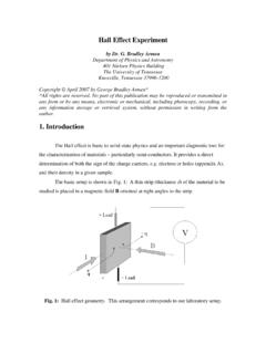
Hall Effect Experiment - University of Tennessee
www.phys.utk.eduAssuming the voltmeter probes are vertically aligned, the voltage difference is zero when B = 0. The current I flows in response to an applied electric field, with its direction established by convention. However, on the microscopic scale I is the result of either

Type CO Overcurrent Relay Instruction Leaflet - ABB
library.e.abb.com** Voltages taken with Rectox type voltmeter. CO-5 LONG TIME AND CO-6 DEFINITE MINIMUM TIME RELAYS. 41-101U Type CO Overcurrent Relay 6 ENERGY REQUIREMENTS CO-7 MODERATELY INVERSE TIME RELAY VOLT AMPERES** Continuous One Second Power At At 3 Times At 10 Times At 20 Times
SERVICE MANUAL - Navistar
bodybuilder.navistar.com3200, 4100, 4200, 4300, 4400, 7300, 7400, 7500, 7600, 7700, 8500, 8600, MXT, RXT Models Built Oct. 1, 2005 to Feb. 28, 2007 — ELECTRICAL CIRCUIT DIAGRAMS