Search results with tag "Karnaugh maps"
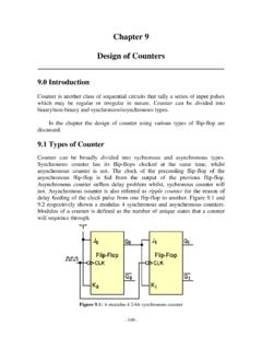
Chapter 9 Design of Counters
staff.utar.edu.myThe Karnaugh maps of the output R 0, S 0, R 1, S 1, R 2, and S 2 are shown in Fig. 9.19, 9.20, and 9.21 respectively. The simplified results are at the bottom of the Karnaugh maps. Figure 9.19: Karnaugh maps of R 0 and S 0 Figure 9.20: Karnaugh maps of R 1 and S 1 Figure 9.21: Karnaugh maps of R 2 and S 2

Digital Electronics
www.learnabout-electronics.orgIntroduction. Digital logic is the foundation, not only of computing but also many other electronic devices and control systems found in ... Section 2.4 Karnaugh Maps. • Constructing Karnaugh maps • Minimising Karnaugh maps • Software for Boolean simplification

Unit – 2 Combinational Logic Circuits
d13mk4zmvuctmz.cloudfront.net• Draw 3- variable and 4- variable Karnaugh maps and use them to simplify Boolean expressions • Understand don’t Care Conditions • Use the Product-of-Sums Method to design a logic circuit based on a design truth table • Perform conversion between SOP and POS 3 - Variable Karnaugh Map Consider a logic equation Y = f(A, B, C).

CHAPTER VIII FINITE STATE MACHINES (FSM)
limsk.ece.gatech.edu• Use Boolean algebra, Karnaugh maps, etc. as normal to simplify. • Draw a register for each state bit. • Draw logic diagram components connecting external outputs to external inputs and outputs of state bit registers (which have the present state). • Draw logic diagram components connecting inputs of state bits (for next
Introduction to Digital Systems - University of California ...
inst.eecs.berkeley.eduprovides only a basic introduction to Boolean algebra – describing it in its entirety would take up an entire textbook. I chose to concentrate on the basics of Boolean algebra, rather than on optimizing concepts like Karnaugh Maps. First we start out with the concept of digital vs. analog. 2. Digital vs. Analog [2]