Search results with tag "Current transformer"
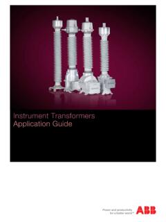
Instrument Transformers Application Guide
library.e.abb.com9.7 Current transformer requirements for CTs according to other standards 127 9.7.1 Current transformers according to IEC 61869-2, class P, PR 127 9.7.2 Current transformers according to IEC 61869-2 class PX, TPS 127 9.7.3 Current transformers according to ANSI/IEEE 128 10. Non Coventional Instrument Transformers 129

3-in-1 Current Transformers - Crompton Instruments
www.crompton-instruments.comA range of 3-in-1 current transformers combine three traditional current transformers in one moulded case. 3-in-1 current transformers can be directly installed next

The Basics of Current Transformers
www.nktechnologies.comCurrent Transformer White Paper The Basics of Current Transformers Ratio ... The CT accuracy applies at the maximum rated secondary burden at 20 time the rated current. The ratio accuracy can be up to four times greater than the listed value, depending on connected burden and fault current. (Typically window,
Principle of operation of CT - IDC-Online
www.idc-online.comCurrent Transformer Principle of operation of CT A current transformer is defined as “as an instrument transformer in which the secondary current is substantially proportional to the primary current (under normal conditions of operation) and differs in phase from it by an angle
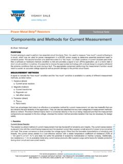
Components and Methods for Current Measurement
www.vishay.comFig. 1 - Ideal current transformer circuit Fig. 2 - Current transformer loss components Rogowski Coil The Rogowski coil (Fig. 3) is similar to a current transformer in that a voltage is induced into a secondary coil that is propo rtiona l to the …

1. CURRENT TRANSFORMERS Oil-paper insulation Gas ...
www.energia.no4 Instrument transformers | High voltage 1. CURRENT TRANSFORMERS Oil-paper insulation Gas insulation Dry insulation › 420 kV Current transformers with gray …

Instrument Transformer Basics - WMEA
wmea.netInstrument Transformer Basics What is an Instrument Transformer? Current Transformer (Sometimes called CTs) It is simply a device unused to measure current by
Lesson 11: Transformer Name Plate Data and Connections
www.engr.siu.eduIdentify transformer polarity using dot and conventional labeling. Explain and interpret information found on transformer name plates. Compare and contrast the performance of three phase transformer connections. Indentify the schematic symbols of potential and current transformer. List characteristics on these devices and explain how

Calculation of the Current Transformer Accuracy Limit Factor
library.e.abb.comCalculation of the Current Transformer 1MRS 755481 Accuracy Limit Factor 1. Scope This document describes the calculation of the actual accuracy limit factor (F a) for protection-type (P) current transformers (CT). First, the calculation of the actual burden of the CT, including connection wires and protection relay impedance, is presented.
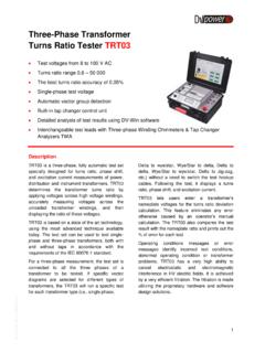
Three-Phase Transformer Turns Ratio Tester TRT03
www.hvtest.co.zaB -T0 0 3 N N-31 7-EN 1 7-0 3-29 3 Current Transformer TRT03 can also be used for verifying turns ratio and polarity of current transformers (CTs). CTs

Application Notes for KCGG High Impedance Protection
www.yipjacks.com4 Vf = maximum voltage that would be produced if CT saturation did not occur. I'f = maximum internal secondary fault current. RCT= current transformer secondary winding resistance. RL = maximum lead burden from current transformer to relay. RST = relay stabilising resistor.

Loop-Powered AC Current Transmitter - CR …
www.crmagnetics.comCR4220 One Element - 4 - 20 mADC Output CR4220 One Element with external current transformer * CR4260 Two Element with external current transformer *

Instrument Transformer Basic Technical Information and ...
www.gegridsolutions.comThe ratio of an instrument transformer is the relationship of its primary rating to its secondary rating. For example, the potential transformer mentioned above having a rating of 480:120 volts will have a ratio of 4:1 and the current transformer having a rating of 400:5 amperes will have a ratio of 80:1. Magnetic Circuits Rating and Ratio

CT1 Current Transformers Ratio / Polarity / Types
www.idc-online.comThe Auxiliary CT is installed as close as possible to the current transformers. This reduces the CT burden by reducing the length of the CT secondary current conductors. CT Shorting Terminal Strips The illustration below shows the termination of a multi …

CROMPTON INSTRUMENTS CURRENT TRANSFORMERS
crompton-instruments.comAbAout TTT EoCnecCbivbycosnAbcyaECnTEcagcnl MR transformers are used to accurately measure high alternating primary currents, converting the primary current into a ...

Protection Basics
r5.ieee.orgNov 18, 2019 · and operation time Current, voltage (I and V), or other quantities Input. ... Electromagnetic Induction Principle . ... Current transformer (CT) Potential transformer (PT) A/D Conversion : A/D Analog signal : Digital signal : 00000001 : …

Fault Finding meter Connections - ND - Home - …
www.northern-design.co.ukFault Finding meter Connections Fault Finding ! ! ! SAFETY NOTE ! ! ! Current transformers operate in opposite way to voltage transformers. A current

Vibration and Shock tests on a typical Current Transformer Set
www.eleq.comNLR-CR-2009-412 3 Summary This document contains the description and the results of vibration and Shock tests, performed for ELEQ Steenwijk B.V. on a typical current transformer set.

August2018. - densokutechno.co.jp
www.densokutechno.co.jpSTANDARDPRODUCTSLIST № Products Model LIST PRICE J.\ * Days for delivery Specifications 39<Auxiliary Transformer> 40 Auxiliary Current Transformer CTS-211 410,000 90Class : 0.1 5A/10-3.1A 41 Auxiliary Voltage Transformer PTS-34 301,600 90Class : …
A Textbook of Electrical Technology Vol. 2 - Theraja - Weebly
www.kurratul.weebly.comCurrent Transformers—Potential Transformers. Induction Motor Classification of AC Motors—induction Motor: General prin- ... phase Induction Motor—WithouI Core Loss—EQuivalent ... Circuit Of an Induction Motor—Power Balance EQuation— Maximum Power Output—Corresponding Slip. 35. Computation And Circle Diagrams

Features - CR Magnetics–Current Transducers, …
www.crmagnetics.com95 Current Transformers F 3500 Scarlet Oak Blvd. St. Louis MO USA 63122 V: 636-343-8518 F: 636-343-5119 Web: http://www.crmagnetics.com E-mail: sales@crmagnetics.com

ELECTRICAL MEASUREMENTS & INSTRUMENTATION
www.vssut.ac.inInstrument Transformers: Potential and current transformers, ratio and phase angle errors, phasor diagram, methods of minimizing errors; testing and applications. Galvanometers: General principle and performance equations of D' Arsonval Galvanometers, Vibration Galvanometer and Ballistic Galvanometer.

Crompton Instruments Class PX Current Transformers
www.crompton-instruments.comProduct codes Part number Ratio Dimensions Class Vk Ωat 75°c A B C 81X-9412-501388 800/5 PX 52 0.35 65 135 65
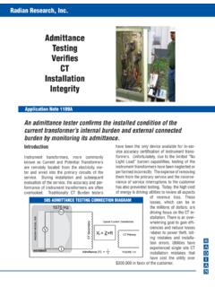
Admittance Testing CT Installation Integrity - Power
www.radianresearch.comThe burden challenge is presented to the in ser-vice current transformer secondary in the form of a known ohmic resistance value that is added

Current Sense Transformers and Inductors - Nuvotem
www.nuvotem.comPrimary Current Ratings to 200 Amps • Mains 50/60Hz Current Transformers • SECTION 7 20kHz to 200kHz Current Sense Inductors and Transformers • Fully RoHS Compliant •

Current transformers (CT's) - MetersUSA
www.metersusa.comCurrent transformers (CT's) provide a simple, inexpensive and yet accurate means of sensing current flow in power conductors. They are available in 3 basic configurations: 1. Ring Core CT's are available for measuring currents from 50 to 5000 amps, with windows (power conductor opening size) from 1" to 8"

Transformer Protection
www.ewh.ieee.orgCurrent Transformer (CT) Principle • CT isolates relay from the HV system • Drastically reduces current Ideally: is = ip / Ns. 5/29/2015 Schweitzer Engineering Laboratories 9 Core and Secondary Winding Example The Current Transformer Equivalent ... • Operation conditions

Current Transformer (CT) Selection Guide - eGauge
www.egauge.neteGauge Systems Article: CT Selection Guide 1 Introduction This guide is intended to help you select the right quantity and type of current transformers (CTs) needed for
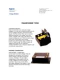
TRANSFORMER TYPES - Te Connectivity
www.cromptonusa.comPotential transformers can be used with voltmeters for voltage measurements or they can be used in combination with current transformers for watt-meter or watt-
Current Transformers - Te Connectivity
www.cromptonusa.comSummary CT's are inexpensive, accurate devices for monitoring current. If properly sized and installed, they will give many years of trouble free service with no adjustments to make. Call Kele for help with your specific applications.
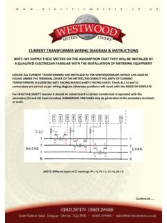
CURRENT TRANSFORMER WIRING DIAGRAM & …
electricmeters.co.ukmarkings on the meter and the CT 6 Always connect k (or S1) to the first terminal of the phase and l (or S2) to the third terminal. The smaller middle terminal is for a voltage connection from that phase 7 Check the RST indicator, this should be on – if it is off one or more phase voltages is missing – if it
Similar queries
CURRENT TRANSFORMER, Current, Current Transformers, Accuracy, Principle of operation of CT, Current Transformer Principle of operation of CT, CURRENT TRANSFORMERS Oil-paper insulation Gas, Transformers, CURRENT TRANSFORMERS Oil-paper insulation Gas insulation, Insulation, Instrument Transformer Basics, Transformer, Phase Transformer Turns Ratio Tester TRT03, Ratio, Polarity, Application Notes for KCGG High Impedance Protection, Loop-Powered AC Current Transmitter, Current Transformers Ratio / Polarity / Types, Close, Operation, Principle, Fault Finding meter Connections, Core, Balance, Features, Crompton Instruments, Current Sense Transformers, Current Sense, Current Transformer (CT) Selection Guide, TRANSFORMER TYPES, Voltage, Meter, Phase, Connection