Search results with tag "Powerdrive"
HOW TO FIND YOUR SERIAL NUMBER ON MODELS …
www.minnkotamotors.comApr 10, 2018 · On the top of the transom bracket MK 1 DC, MK 2 DC, MK 3 DC ... PowerDrive / PowerDrive V2 / Riptide PowerDrive Bottom of the foot pedal Inside the mount base below the motor rests CoPilot System (Legacy) Terrova / Riptide Terrova The inside of the side plate
FRESHWATER MOTORS
www.minnkotamotors.comPowerDrive 68/BT PowerDrive 54/BT Pontoon 70/H Pontoon 55/H Quick Release Bracket Quick Release Bracket Pontoon Latch & Door Pontoon Latch & Door Side-to-Side/Electric Foot Pedal Tilt Twist Tiller Tilt Twist Tiller 68 54 70 55 24 12 24 12 Variable Variable 5 FWD/3 REV 5 FWD/3 REV Yes Yes — — 48" 48" 52" 52" Weedless Wedge 2 Weedless Wedge 2 ...

SECTION 11–ELECTRICAL SYSTEM AND TESTING
blockbustergolfcarts.comPage 11-2 1998/1999 PowerDrive System 48 Vehicle Maintenance and Service Supplement 11 ELECTRICAL CIRCUITS There are four separate circuits which make up the electrical system of the PowerDrive System 48 vehicle: 1) the control circuit, 2) the power circuit, 3) the speed control circuit, and 4) the charge circuit. A reverse buzzer
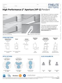
High Performance 2 Aperture (HP-2) Pendant
www.finelite.comELD-DMX - EldoLED POWERdrive, 0.1% ELD-DMX-TW - EldoLED POWERdrive, 0.1% (Tunable White) Lutron Driver Options LUT-ES1 - Lutron, Ecosystem 1% LUT-2W - Lutron, 2-wire (120V only) 1% LUT-TW - Lutron T-Series, EcoSystem 0.1% (Tunable White) See Page 3 for additional driver options and details FA50 - Fully Adjustable 50" (standard) FA100 - Fully ...
OWNER’S MANUAL FOR POWERDRIVE 3 - Club Car
xrtdealers.clubcar.comSafety Details Page 4 PowerDrive 3 Battery Charger Owner’s Manual SAFETY DETAILS ý WARNING • This manual should be read completely before attempting to use or service the charger.
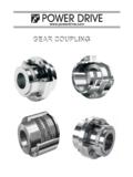
GEAR COUPLINGGEAR COUPLING - PowerDrive LLC
www.powerdrive.comOrder Today ! Phone / Fax / Visit / www.powerdrive.com GEAR COUPLING Selection Procedure TABLE 1 — Torque and Horsepower Ratings STANDARD SELECTION METHOD The standard selection method can be used for most motor,
GEAR COUPLINGGEAR COUPLING - PowerDrive
www.powerdrive.com3. REQUIRED MINIMUM COUPLING RATING 4.FindDesignHp: 5.TYPE 6. SIZE CHECK Select a gear coupling to connect a 500 HP, 1170 RPM electric motor to a drive high speed shaft of a maneuvering winch. Maximum shaft separation is .250". Motor shaft diameter is 3.375" and keyway is.875" x .438". Winch shaft diameter is 3.000" and keyway is 50" x
![INDEX [www.powerdrive.com]](/cache/preview/e/2/2/a/5/8/1/7/thumb-e22a581767b5648f59c0ac894ed62031.jpg)
INDEX [www.powerdrive.com]
www.powerdrive.comINDEX Note: All Measurement and Dimensions are In Inch PAGE # YOKE ROLLER TYPE BEARING CAM FOLLOWER BEARING. NEEDLE ROLLER BEARING TRACK ROLLER BEARING
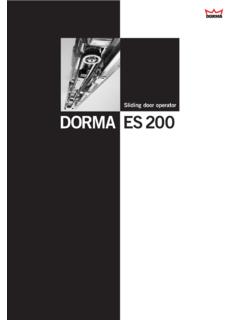
Sliding door operator DORMA ES200
products.dorma.com4 Sliding door operator DORMA ES 200 DORMA PowerDrive System for particularly punchy performance The door variants on this page are shown as corridor installation with LM girder.
SECTION 11–ELECTRICAL SYSTEM AND TESTING
blockbustergolfcarts.com1998/1999 PowerDrive System 48 Vehicle Maintenance and Service Supplement Page 11-1 SECTION 11–ELECTRICAL SYSTEM AND 11 TESTING GENERAL INFORMATION
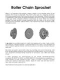
Roller Chain Sprocket - PowerDrive LLC
www.powerdrive.comWhen it is imperative that angular velocity rotation to be constant some of the positive drive must be employed. The chain is that type of a wrapping connector
POWERDRIVE BATTERY CHARGER OWNER’S MANUAL
xrtdealers.clubcar.comGeneral Information PowerDrive Battery Charger Owner’s Manual Page 7 IQ System Vehicles: At one hour and at two hours into the charge cycle, the charger will shut off in order to run a self-diagnostic program (ammeter will drop to zero).