Search results with tag "200 amp"

100-200 Amp Fusible Pullout Switch (200 Amp Frame Size)
www.boltswitch.com100 - 200 AMP PULL OUT SWITCH (200 AMP FRAME SIZE) These devices are load-break switches designed primarily for installa tion in pa nelboard s, contr ol panels, a nd met er bank s.
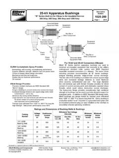
25-kV Apparatus Bushings Bulletin 1025-200 200 Amp, 600 ...
www.elliott-industries.com25-kV Apparatus Bushings “B” Series (bolt-in) for Elbow to Air-Insulated Service 200 Amp, 600 Amp, 900 Amp and 1250 Amp Elastimold® Bulletin
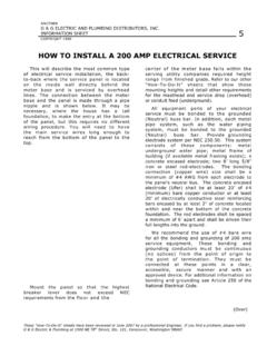
HOW TO INSTALL A 200 AMP ELECTRICAL SERVICE
groverelectric.comHOW TO INSTALL A 200 AMP ELECTRICAL SERVICE This will describe the most common type of electrical service installation, the back-to-back where the service panel is located on the inside wall directly behind the meter base and is serviced by overhead lines. The connection between the meter base and the panel is made through a pipe nipple and is ...

Switchgear Prod Guide0082003 - TNB.COM
www.tnb.comMVI. FRONT VIEW SINGLE-PHASE FRONT VIEW THREE-PHASE 200 AMP WELLS 600 AMP BUSHINGS. Elastimold MVI Molded Vacuum Fault Interrupters are devices capable of making, carrying and automatically interrupting
Grounding & Bonding — Why it is done And How to Install ...
www.adamselectric.coopbase is mounted outside and a 200 Amp Main Breaker Panel is located immediately adjacent inside the home. SERVICE EQUIPMENT The Code defi nes Service Equipment as the necessary equipment, usually consisting of a circuit breaker(s) or switch(es) and fuse(s) and their accessories, connected to …

METERING INSTALLATION REQUIREMENTS
www.bia.govWhenever any electrical wiring for service connection is installed whether regulated by inspection ... 200 AMP ALL IN ONE METER CAN - RESIDENTIAL Meter Compartment Sealable Customer Panel Customer CT's ... It is the Customer’s responsibility to install conduit and wiring between the meter location and

How to manage a 60 to 200 amp load using a SMM Module …
www.pspproducts.netStep One: Remove the spade terminal with the BLUE, RED and BLACK wires shown from the contactor Blue wire from control board RED wire from control board