Search results with tag "Transverse"

State Plane Coordinate System of 1983
www.ngs.noaa.govdefined within SPCS 83: Lambert conformal conic, transverse Mercator, and oblique Mercator. A section on t~a Universal Transverse Mercator (UTM) projection is included. UTM is a derivative of the general transverse Mercator projection as well as another projection, in addition to SPCS 83, on which NAD 83 is published by NGS. 1. INTRODUCTION

Chapter 7: Transverse Shear
courses.physics.illinois.eduTransverse loading of beams When a transverse shear load is applied, it tends to cause warping of the cross section. Therefore, when a beam is subject to moments and shear forces, the cross section will not remain plane as assumed in the derivation of the bending stress formula.

Maps and Cartography: Map Projections - Ball State University
lib.bsu.edu2) Transverse Mercator The Transverse Mercator projection is a cylindrical projection often used to portray areas with larger north-south than east-west extent. Distortion of scale, distance, direction and area increase away from the central meridian. The Universal Transverse Mercator (UTM) projection is

STRUCTURAL DESIGN HIGHLIGHTS OF ACI 318-19 PART 2 of …
asceneworleans.orgNov 14, 2019 · TRANSVERSE REINFORCEMENT 11.7.3.1 Spacing s of transverse reinforcement in cast-in-place walls shall not exceed the lesser of 3h and 18 inches. If shear reinforcement is required for in-plane strength, spacing of longitudinal reinforcement shall not exceed l w /5. 11.7.3.2 Spacing s of transverse bars in precast walls shall not exceed the
CALTRANS SEISMIC DESIGN CRITERIA
dot.ca.govtransverse direction to include overturning effects 3.6.3 5.3.7.3 Deleted equation for “Nominal Shear Reinforcement Capacity” of Pier walls 3.8.2 5.3.8 Section title changed from “Lateral Reinforcement…” to “Transverse Reinforcement…” 5.3.8.1 Added design provisions for transverse reinforcement

Duct Construction Standards
sweets.construction.comAll transverse joints, longitudinal seams and duct wall penetrations All transverse joints and longitudinal seams Transverse Joint B C 4” w.g. and up 3” w.g. 2” w.g. In addition to the above, any variable air volume system duct of 1” and 1/2” w.g. construction class that is upstream of the VAV boxes shall meet Seal Class C. J 24 26T

Design of Columns
site.iugaza.edu.psthis transverse reinforcement is in the form of ties, the column is called “tied”. If the transverse reinforcement is in the form of helical hoops, the column is called “spirally reinforced”. Since failure of columns often cause extensive damage, they are designed with a higher factor of
Topographic Maps: The basics - NRCan
www.nrcan.gc.ca• universal transverse mercator (UTM) projection (easting/northing) • geographic: degrees and minutes (longitude/latitude) The projection used for topographic maps is UTM. The UTM grid is a square grid system of lines depicted on maps and based on the transverse . mercator projection.

DESIGN OF SLABS - DR. HILTON WEBPAGE
drhilton.weebly.comsupport, transverse reinforcement is not necessary where there is no transverse bending moment. The spacing of principal reinforcement bars should not exceed three times the overall depth of slab (3h) or 400 mm whichever is the lesser. For secondary reinforcement the spacing should not exceed 3.5h or 450 mm whichever the lesser.
2021 BILLING AND CODING GUIDE HERNIA & ABDOMINAL …
asiapac.medtronic.com19368 Breast reconstruction with transverse rectus abdominis myocutaneous flap (TRAM), single pedicle, including closure of donor site; with microvascular anastomosis (supercharging) Facility Only : $2,232 Inpatient Procedures, not reimbursed in outpatient or ASC by Medicare 19369 Breast reconstruction with transverse rectus
Detailing of Reinforcement in Concrete Structures
www.engineersaustralia.org.auΣAtr.min = cross-sectional area of the minimum transverse reinforcement, which may be taken as 0.25As for beams and 0 for slabs As = cross-sectional area of a single bar of diameter db being anchored K = is a factor that accounts for the position of the bars being anchored relative to the transverse reinforcement, with values given below: ...

5 Longitudinal and Transverse Properties of Composites
nanoed.tul.cztwo transverse directions are denoted as T or 2 and S or 3 respectively. If the composite is in the form of a sheet or plate with the fibers lying in a plane parallel to the sheet, then the T or 2-direction lies in this plane. The third direction, which is parallel to the thickness of the plate is

Design of Anchor Reinforcement in Concrete Pedestals
www.construccionenacero.comtransverse reinforcement (ties) did not increase the side-face blowout capacity (DeVries et al. (1998)). Large amount of transverse reinforcement installed near the anchor head only increased the magnitude of load that was maintained after the side-face blowout failure occurred.

ANCHORAGE OF TRANSVERSE REINFORCEMENT IN …
www.nzsee.org.nz165 ANCHORAGE OF TRANSVERSE REINFORCEMENT IN RECTANGULAR REINFORCED CONCRETE COLUMNS IN SEISMIC DESIGN H. Tanaka1, R. Park2, B. McNamee3 SYNOPSIS Four reinforced concrete columns with 400 mm (15.7 in) square cross
Design of confinement reinforcement for RC columns
www.sefindia.orgPurpose of transverse reinforcement Transverse reinforcement are specified in design codes for beams and columns to serve the following four functions: (a) to prevent buckling of longitudinal reinforcing bars, (b) to resist shear forces and to avoid shear failure, (c) …
STANDARD PLAN S FOR PUBLIC WORKS CONSTRUCTION
www.dpw.lacounty.gov152-2 rectangular frame and cover traffic striping ... 305-3 grating catch basin -alley (transverse) 30fr3 curb opening catch basin at driveway ... 640-4 reinforced concrete stairway. section 1 ree m rovemen s. gonvef~tional symbols fq~ existing topography curb curb and gutter

Cracks and Crack Control in Concrete Structures
www.pci.orgof reinforcement needed for crack width control. Causes of Cracking During Concrete Hardening Concrete cracking can develop during the first days after placing and before ... Transverse cracks due to temperature, creep and shrinkage effects are fre-quently found in the relatively thin

Stresses: Beams in Bending - MIT OpenCourseWare
ocw.mit.edutransverse displacement as a function of position along the beam. Our exploration of the behavior of beams will include a look at how they might buckle. Buckling is a mode of failure that can occur when member loads are well below the yield or fracture strength.
2. Design of Welded Connections - American Welding Society
app.aws.orgTransverse fillet welds in lap joints transferring stress between axially loaded parts shall be double-fillet welded (see Figure 2.5) ex-cept where deflection of the joint is sufficiently re-strained to prevent it from opening under load. 2.4.8.2 Minimum Overlap. The minimum overlap of parts in stress-carrying lap joints shall be five times
Chapter 11. Coordinate Systems - umb.edu
www.faculty.umb.eduaxis (equatorial), at 90 degrees to it (transverse), or at any other angle (oblique). • A projection that preserves the shape of features across the map is called conformal. • A projection that preserves the area of a feature across the map is called equal area or equivalent. • No flat map can be both equivalent and conformal. Most fall

Section 15 Concrete Reinforcement
www.dot.ny.govConcrete Reinforcement 15.1 Introduction This section is intended to aid the bridge designer and detailer in the area of concrete reinforced design and detailing. The tables in this section simplify the design and detailing of concrete ... Transverse Bars (Top of Slab) Class B (Not Top Bars) N

Chapter 2 Reading Topographic Maps and Making Calculations
www.honolulu.hawaii.eduUniversal Transverse Mercator (UTM) (edges of map) Prior to 1978, USGS topographic maps used blue tick marks along the edge of the map to illustrate where the UTM grid lines were located. Since 1978, USGS topographic maps actually show UTM grid lines (black) on the map and the coordinate values are in the margin. On USGS topographic maps,
MANUAL OF THE STRUCTURE AND BRIDGE DIVISION
www.virginiadot.org09.TOC Chapter 9 – Transverse Section 10.TOC Chapter 10 – Concrete Deck Slab 11.TOC Chapter 11 – Steel 12.TOC Chapter 12 – Prestressed and Post-Tensioned Concrete 13.TOC Chapter 13 – Bearings 14.TOC Chapter 14 – Joints 15.TOC Chapter 15 – Pier Details 16.TOC Chapter 16 – Intentionally Left Blank
CT transverse anatomy - Nuclear medicine
gamma.wustl.edu2.Inferior Vena Cava 3. Ureter 4.Left Kidney 5.Small Bowel 6.Cecum 6a. Appendix 7.Descending Colon 8. Psoas Muscle 9. Erector Spinae Muscle 10.Rectus Abdominus Muscle

Wood Handbook--Chapter 4--Mechanical Properties of Wood
www.fpl.fs.fed.usAging 4–41 Exposure to Chemicals 4–41 Chemical Treatment 4–41 ... the transverse to axial strain is called Poisson’s ratio. The ... ure of the combined strength and toughness of wood under bending stresses. Compressive strength parallel to grain—Maximum

Classification of Malocclusion - Columbia University
www.columbia.eduExamining the transverse dimension allows us to evaluate the intermolar and intercanine widths and determine which arch is the offending unit. Posterior crossbites can be unilateral or bilateral. A Functional Crossbite results from an occlusal interference that requires the mandible to shift
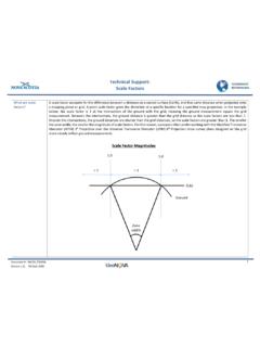
Technical Support: Scale Factors - Nova Scotia
geonova.novascotia.caMercator (MTM) 3⁰ Projection over the Universal Transverse Mercator (UTM) 6⁰ Projection since survey plans designed on the grid more closely reflect ground measurements. Technical Support: Scale Factors 2 Document # : NSCRS_TS0006 Version 1.1, 06 Sept 2016 What is the ...
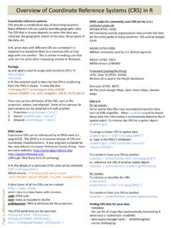
Overview of Coordinate Reference Systems (CRS) in R
www.nceas.ucsb.eduUniversal Transverse Mercator (UTM) The UTM projection is commonly used in research because it tends to be more locally accurate, and furthermore, it has attributes that make the estimating distance easy and accurate. Positions are described using Easting and Northing coordinates. The mercator projection preserves angles and direction, but

4.4 Electrical conductivity of minerals and rocks
appliedgeophysics.berkeley.educonductivity perpendicular to the bedding plane, the transverse conductivity, is unaffected by small fracture porosity and so the vertical axis can be interpreted as the coefficient of anisotropy. It is clear that small fracture porosity can have an enormous effect on anisotropy. For example in a rock of 0.1 porosity and 0.01

EL SISTEMA DE COORDENADAS UTM - RiuNet repositorio UPV
riunet.upv.es4.1. Lectura de las coordenadas UTM. 5. Cierre 6. Bibliografía 4 Desarrollo El sistema de coordenadas UTM (Universal Transverse Mercator) es un sistema de proyección cartográfico basado en cuadrículas con el cual se pueden referenciar puntos sobre la superficie terrestre.

2-5 좌표계와 좌표변환
aia.bizadmin.co.kr3) UTM (Universal Transverse Mercator) - 2차원 평면 좌표계이며 UTM 구역(zone)으로 구성되어 있다. 경도로 6도마다 UTM 구역 번호가 부여되며 구역번호는 경도 180도 지역인 베링해 부근에서 동쪽으로 1에서 60까지 부여한다.

LOAD DISTRIBUTION
site.iugaza.edu.psBy lateral we imply a direction transverse to the main reinforcement. Distribution reinforcement is located in the bottom of the deck slab. To determine the amount of distribution steel required, the amount of main reinforcement needed is multiplied by a specified percentage. 1. Main reinforcement perpendicular 2. Main reinforcement is parallel

COOLER RETURN LINE CHART - Lubegard
www.lubegard.comNova 4 Speed (Toyota A240E) Bottom Spectrum (Toyota A130L) Bottom Sprint (MX17) Bottom AF33‐5: Rear: HONDA: Transmission Location: 2, 3, 4 and 5 Speed Line Nearest: Differential L4, ML4A Line On Case (Not Bellhousing) ... (Transverse Engine) Bottom: SATURN: Transmission Location: All Models Line Closest: to Spin-On Filter: SUBARU: Transmission:
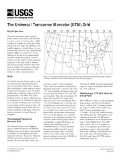
The Universal Transverse Mercator (UTM) Grid
pubs.usgs.govlar grid consisting of two sets of straight, parallel lines, uniformly spaced, each set perpendicular to the other. This grid is designed so that any point on the map can be designated by its latitude and longitude or by its grid coordinates, and a reference in one system can be converted into a ref-erence in another system. Such grids are

Techniques and Procedures for Collecting, Preserving ...
www.for.gov.bc.ca•Topographic maps and location information should include Universal Transverse Mercator (UTM) locations or latitudes and longitudes. •Small altimeter for measuring elevations. •Gardening gloves to prevent injury when handling irritating or thorny specimens. •Strong plastic bags for storing branches or carrying individually bagged
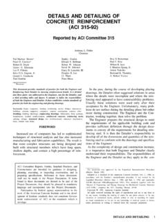
DETAILS AND DETAILING OF CONCRETE REINFORCEMENT …
www.globaldesignsolutions.comFig. 17-Example of transverse reinforcement in col-umns, pg. 315-37 Fig. l&-Typical ductile frame-spandrel joint details, pg. 315-38 Fig. 19-Boundary members, pg. 315-39 Fig. 20-Recommended layout for placing drawings, pg. 315-39 Fig. 21-Typical bar lists for buildings, pg. 315-40 Fig. 22-Typical bar list for highway structures, pg. 315-41

REINFORCED CONCRETE DESIGN TO EC2
people.utm.myREINFORCED CONCRETE DESIGN TO EC2 FORMULAE AND DESIGN RULES FOR TEST AND FINAL EXAMINATION ... - Procedure for Calculating Transverse Shear Reinforcement in Flanged ... MS EN 1992-1-1: 2010) - Table 7.4N: Basic span/effective depth ratio (Typical values for rectangular section for steel grade f yk = 500 N/mm 2 and concrete class C30/35) 9.0 ...

Single Precast Reinforced Concrete Box Culvert Standards
iowadot.govTransverse Reinforcement Bottom of Form Reinforcement Longitudinal maximum of 48 inches. of nylon boots when spaced at a Plastic spacers may be utilized in lieu Nylon boots on every fourth wire. Bottom of Form Reinforcement Longitudinal Steel Form or Equal or Bevel Optional Small Radius As1, As7 or As8 As5

Simplified Highway Capacity Calculation Method for the ...
www.fhwa.dot.govTABLE OF CONTENTS . CHAPTER 1. INTRODUCTION .....1 CHAPTER 2. DEVELOPMENT OF CAPACITY COMPUTATION METHODS.....3. REVIEW HIGHWAY ECONOMIC REQUIREMENTS SYSTEM CAPACITY ... rate at which vehicles can be expected to transverse a point or a uniform section of lane or roadway during a given time period under prevailing …

ESSENTIAL TECHNICAL DATA ON STEEL REINFORCEMENT
www.libertygfg.comSteel Reinforcement Institute of Australia (SRIA) Technical Notes 62 OneSteel Reinforcing Branch Locations 63. 5 www.reinforcing.com 5 In 2015, the Green Building Council of Australia updated its Design and As Built Guidelines. ... K & λ account for transverse reinforcement - 2 …
Seismic Design Criteria Version 2 - Caltrans
dot.ca.govModified the provision for transverse reinforcement for Type II shafts : 6.2.2: 6.1.1. Adopted a new “Soil Classification” “Competent” soil now classified as “Class S1” soil All non-Competent soils (Marginal, Poor, Soft, potentially liquefiable, and soil susceptible to lateral spreading) now

Cartes topographiques : Les éléments de base - NRCan
www.nrcan.gc.ca• la projection de Mercator transverse universelle (UTM) (abscisses et ordonnées); • les coordonnées géographiques exprimées en degrés et en minutes (longitude et latitude). Les cartes topographiques s’appuient sur la projection UTM. Le quadrillage UTM est …

TRANSVERSE MERCATOR AND LAMBERT CONFORMAL …
www.sco.wisc.eduTransverse Mercator Projections (After Stem (1989)). Transverse Mercator projections are based upon right cylinders whose axes lie in the equatorial plane and pass through the center of the reference ellipsoid.
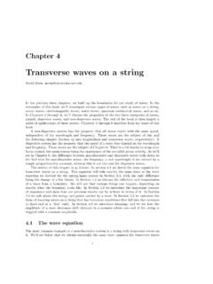
Transverse waves on a string - Harvard University
scholar.harvard.eduIn section 4.1 we derive the wave equation for transverse waves on a string. This equation will take exactly the same form as the wave equation we derived for the spring/mass system in Section 2.4, with the only difierence being the change of a few letters. In Section 4.2 we discuss the re°ection and transmission of a wave from a boundary.

Transverse Vibration of Beams - MaplePrimes
www.mapleprimes.comThe transverse or lateral vibration of a thin uniform beam is another vibration problem in which both elasticity and mass are distributed. Consider the moments and forces acting on the element of the beam shown in Fig. 4.2. The beam has a cross-sectional area A, flexural rigidity EI, material of density p and Q is the shear force.

TRANSVERSE MERCATOR PROJECTIONS AND U.S.
www.geo.utexas.eduThis paper explains the characteristics of Transverse Mercator projections, the relationship of plane grids to USGS map cells, and the reasons DRG’s and other USGS digital products are projected on the UTM.
Similar queries
TRANSVERSE MERCATOR, Mercator, Universal Transverse Mercator, Transverse, Transverse Mercator projection, Projection, Transverse reinforcement, Of transverse reinforcement, Reinforcement, Of transverse, CALTRANS, Topographic Maps: The basics, Topographic maps, DESIGN, Detailing of Reinforcement in Concrete Structures, Of transverse reinforcement in, OF TRANSVERSE REINFORCEMENT IN RECTANGULAR REINFORCED CONCRETE, REINFORCED CONCRETE, Design of confinement reinforcement for RC columns, Of transverse reinforcement Transverse reinforcement, Rectangular, Crack Control in Concrete Structures, Bending, MIT OpenCourseWare, CHAPTER, Transverse Section, CT transverse anatomy, Left, Aging, Toughness, Columbia University, Coordinate Reference Systems, Coordinates, 4.4 Electrical conductivity of minerals and, UTM Universal Transverse Mercator, Speed, HONDA, 5 Speed, Grid, System, AND DETAILING OF CONCRETE REINFORCEMENT, Concrete, TABLE OF CONTENTS, Section, Seismic Design, Cartes topographiques : Les éléments de base, Mercator transverse, TRANSVERSE MERCATOR AND LAMBERT CONFORMAL, Wave