Search results with tag "Current mode"

Low power offline switched-mode power supply primary …
www.st.comFigure 5. presents the internal current mode structure. Figure 5. Internal current control structure The power MOSFET delivers a sense current I s which is proportional to the main current Id. R2 receives this current and the current coming from the FB pin. The voltage across R2 is then compared to a fixed reference voltage of about 0.23 V.

Understanding Buck Power Stages Mode Power Supplies
www.ti.comUnderstanding Buck Power Stages in Switchmode Power Supplies 3 2 Buck Power Stage Steady-State Analysis A power stage can operate in continuous or discontinuous inductor current mode. Continuous inductor current mode is characterized by current flowing continuously in the inductor during the entire switching cycle in steady state operation.

NCP12700 - Current Mode PWM Controller, Ultra Wide Input
www.onsemi.comPWM Controller, Input Current Mode, Ultra Wide NCP12700 The NCP12700 is a fixed frequency, peak current mode, PWM controller containing all of the features necessary for implementing single−ended power converter topologies. The device features a high voltage startup capable of operating over a wide input range and

Practical Feedback Loop Analysis for Current-Mode …
www.ti.comSLVA636 . Practical Feedback Loop Analysis for Current-Mode Boost Converter 3 . Figure 2 shows the nature of the current loop oscillation. This …

UC3842B - High Performance Current Mode Controllers
www.onsemi.comCurrent Mode Controllers UC3842B, UC3843B, UC2842B, UC2843B ... • Latching PWM for Cycle−By−Cycle Current Limiting ... This device contains latch-up protection and exceeds 100 mA per JEDEC Standard JESD78. UC3842B, UC3843B, UC2842B, UC2843B www.onsemi.com 3

Switch Mode Power Supply (SMPS) Topologies
ww1.microchip.comSep 10, 2007 · ripple requirement. Generally , to implement the current mode control, the ripple current at the inductor should be at least 30% of the full load current. FEED-FORWARD CONTROL In a buck converter, the effect of input voltage variation on the output voltage can be minimized by implementing input voltage feed-forward control. It is

LT8357 (Rev. 0)
www.analog.comand Flyback Controller The LT®8357 is a wide input range, current mode, DC/DC controller which can be configured as a boost, SEPIC or flyback converter. The LT8357 drives a low side N-channel power MOSFET with 5V split gate drive. The current mode architecture allows adjustable and synchronizable 100kHz

High performance current mode PWM controller
www.st.comuc2842b/3b/4b/5b uc3842b/3b/4b/5b march 1999 high performance current mode pwm controller. trimmed oscillator for precise fre-. quency control oscillator frequency guaranteed

Digital Peak Current Mode Control With Slope …
www.ti.comApplication Report SPRABE7A– April 2012 Digital Peak Current Mode Control With Slope Compensation Using the TMS320F2803x Richard Poley and Ali Shirsavar.....

LT3845 - High Voltage Synchronous Current Mode …
www.analog.comLT3845 1 3845fd TYPICAL APPLICATION FEATURES APPLICATIONS DESCRIPTION High Voltage Synchronous Current Mode Step-Down Controller with Adjustable Operating Frequency

Topologies for switch mode power supplies
www.st.comTOPOLOGIES FOR SWITCHED MODE POWER SUPPLIES by L. Wuidart the rectifier, different types of voltage ... ISOLATED SWITCHING REGULATORS According to the position of the switch and AN513/0393 1/18. ... corrected with a current mode PWM control

NCP1252 - Current Mode PWM Controller for Forward and ...
www.onsemi.comCurrent Mode PWM Controller for Forward and Flyback Applications The NCP1252 controller offers everything needed to build cost− effective and reliable ac−dc switching supplies dedicated to ATX power supplies. Thanks to the use of an internally fixed timer, NCP1252 detects an output overload without relying on the auxiliary Vcc.

Switching Power Supply Topology Voltage Mode vs. …
www.ti.comSwitching Power Supply Topology Voltage Mode vs. Current Mode by: Robert Mammano Unitrode IC Corporation has, since its inception, been active in the development of leading-edge
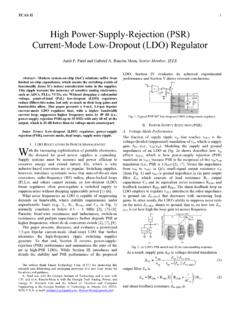
High Power-Supply-Rejection (PSR) Current-Mode Low …
rincon-mora.gatech.edupower-supply rejection PSR) up to 10 MHz with only 68 nF at the output, which is 20 dB better than its voltage-mode counterpart. Index Terms : Low-dropout A.(LDO) regulator, power-supply

Is Now Part of - ON Semiconductor
www.onsemi.comAN4107 APPLICATION NOTE 4 ©2001 Fairchild Semiconductor Corporation 2-4. Zero Current Detector FAN7527 operates as a critical conduction current mode
Fixed Frequency 99% Duty Cycle Peak Current Mode …
www.ti.comTPS51220 www.ti.com SLVS785C –OCTOBER 2007–REVISED JULY 2009 ELECTRICAL CHARACTERISTICS over operating free-air temperature range, EN = 3.3V, VIN = 12V, V5SW = 5V (unless otherwise noted)

NCP1200 - PWM Current-Mode Controller for Low …
www.onsemi.comNCP1200 www.onsemi.com 3-+-+-+ 250 ns L.E.B. 40, 60 or 100 kHz Clock Overload? Fault Duration Skip Cycle Comparator Vref 1 V 5.2 V Q Flip−Flop DCmax = 80% 20 k …

LM5034 High Voltage Dual Interleaved Current Mode ...
www.ti.comLM5034 www.ti.com SNVS347A – FEBRUARY 2005– REVISED APRIL 2013 PIN DESCRIPTIONS PIN NAME DESCRIPTION APPLICATIONS INFORMATION 1 OVLP Active Clamp Overlap Adjust An external resistor (10 kΩto 100 kΩ) sets the overlap time of the active clamp

NCP1336 - Quasi-Resonant Current Mode …
www.onsemi.comNCP1336A/B www.onsemi.com 2 PIN FUNCTION DESCRIPTION Pin No. Pin Name Function Pin Description 1 OPP Adjust the Over Power Protection A negative voltage applied to this pin reduces the internal maximum peak
UCx84x Current-Mode PWM Controllers
www.ti.com6 UC1842, UC2842, UC3842, UC1843, UC2843, UC3843 UC1844, UC2844, UC3844, UC1845, UC2845, UC3845 SLUS223E –APRIL 1997–REVISED JANUARY 2017 www.ti.com Product Folder Links: UC1842 UC2842 UC3842 UC1843 UC2843 UC3843 UC1844 …

TPS4021x-Q1 4.5-V to 52-V Input, Current-Mode Boost ...
www.ti.com1 2 3 4 10 9 8 7 RC DIS/EN COMP SS VDD ISNS GDRV GND TPS40210-Q1 V OUT V IN 5 FB 6 BP R SENSE Product Folder Sample & Buy Technical Documents Tools & Software Support ...
'Seminar 800 Topic 7 - Control Loop Design' - TI.com
www.ti.comLloyd Dixon margin. Thus a phase lag of 117° at fc corresponds to a 63° phase margin. Fig. 1 shows the gain -phase plots of two aver-age current mode control loops and their transient
Similar queries
Power, Mode power, Current mode, Current control, Current, MODE POWER SUPPLIES, Power Supplies, SWITCHING, Current Mode PWM Controller, PWM controller, Current-Mode, Mode, Input, Flyback Controller, Controller, Flyback, Frequency, Current Mode Control With Slope Compensation Using the TMS320F2803x, Current Mode Step, Control, Switching Power Supply Topology Voltage Mode, High Power-Supply-Rejection (PSR) Current-Mode, Supply rejection, Supply, Is Now Part of, Fixed Frequency, High Voltage, NCP1336, TPS4021x-Q1 4.5-V to 52-V Input, Current-Mode, Q1 V, Seminar 800 Topic 7 - Control Loop Design