Search results with tag "Pin 3"

JTAG interface connection (20 pin)
www.mperl.comPin 3 (TRST) should be connected to target CPUs TRST pin (sometimes called NTRST). J-Link will also work if this pin is not connected, but you may experience some limitations when debugging. TRST should be separate from the CPU Reset (pin 15) Pin 11 (RTCK) should be connected to RTCK if available, otherwise to GND.

Motherboard Pin - Asus
dlcdnets.asus.comMotherboard Pin Definition 1-5 3. USB device wake-up (3-pin USBPWF) Set these jumpers to +5V to wake up the computer from S1 sleep mode (CPU stopped, DRAM refreshed, system running in low power mode) using the connected USB devices. Set to +5VSB to wake up from S3 and S4 sleep modes (no power to CPU, DRAM in slow
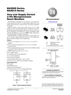
MAX809S - Very Low Supply Current 3-Pin Microprocessor ...
www.onsemi.comMAX809 Series, MAX810 Series www.onsemi.com 3 PIN DESCRIPTION Pin No. Symbol Description 1 GND Ground 2 RESET (MAX809) RESET output remains low while VCC is below the reset voltage threshold, and for a reset timeout period after VCC rises above reset threshold 2 RESET (MAX810) RESET output remains high while VCC is below the reset voltage threshold, and for a reset timeout
(CP37D - Pin 3/2014) (Sila baca nota di muka sebelah ...
www.hasil.gov.my(Sila baca nota di muka sebelah sebelum mengisi borang ini) (Please read the notes overleaf before completing this form) LEMBAGA HASIL DALAM NEGERI MALAYSIA