Search results with tag "Link connector"

VW Online Technical Library - Diagnostic Trouble Codes (DTC)
passat.pavsweb.comData Link Connector (DLC). For location of the data link connector, see Maintenance section. Several aftermarket scan tools and computer programs are also capable of retrieving this information in this factory mode. The factory mode also allows the scan tool to be used for other system diagnostic functions and information retrieval.

Audi Diagnostic Trouble Codes DTC Table - General
www.vaglinks.comAudi Diagnostic Trouble Codes (DTCs) and data can be retrieved with VW/Audi Factory Scan Tools such as the VAG 1551, VAG 1552, or the new diagnostic computer VAS 5051 through a Data Link Connector (DLC). For location of the data link connector, see Maintenance section. Several aftermarket scan tools and computer programs are

Table of Contents - on-board diagnostic s
www.onboarddiagnostics.com4. OBD II CONNECTOR-Connects the Code Scanner to the vehicle’s Data Link Connector (DLC). 3.2 Product Specifications y Display-Backlit LCD, 2 lines, 8 characters each 7 y Operating Temperature - 0 to 50℃ (﹣32 to 122℉) y Storage Temperature - ﹣20 to 70℃ (﹣4 to 158℉) y Power- DC12V provided via the vehicle’s battery y Dimensions:

chapter 1 THE DIAGNOSTIC PROCESS - Pearson
www.pearsonhighered.comfollow if no diagnostic trouble code has been set. 7. List the steps in most manufacturers' diagnostic routines. 8. Describe how to verify the repair and conduct a universal drive cycle. 9. Describe how to run OBD-II monitors on a light duty diesel vehicle. LEARNING OBJECTIVES 1 Data link connector (DLC) 7 Drive cycle 20 Flash code retrieval 11

EVAP SYSTEM MONITOR DRIVE CYCLE INSTRUCTIONS
ww2.justanswer.comSep 10, 2010 · 1. Connect the Scan Tool to the data link connector (DLC). Use the Scan Tool to clear any stored DTC's and to reset the Onboard Diagnostic Monitors. Bring up the Readiness Code for the EVAP System Monitor. 2. Start the engine (cold); IAT PID from 40-100ºF (this step requires a key "off" period of at least 8 hours). 3.

OBDII/EOBD Code Reader (00-) 3388
www.free-instruction-manuals.commanual thoroughly before operating your code reader. The safety messages ... The Data Link Connector (DLC) is a standard 16-pin interface located under the dashboard on the driver’s side of the passenger compartment. If the DLC is not ... A. OBD II Cable - provides communication for vehicle DLC.
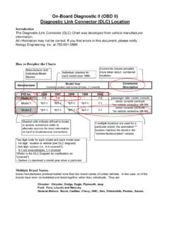
Connector Location dlc - nology.com
www.nology.comOn-Board Diagnostic II (OBD II) Diagnostic Link Connector (DLC) Location Introduction The Diagnostic Link Connector (DLC) Chart was developed from vehicle manufacturer