Search results with tag "Industrial automation wiring and grounding"

1770-4.1, Industrial Automation Wiring and Grounding ...
literature.rockwellautomation.com6 Industrial Automation Wiring and Grounding Guidelines Publication 1770-4.1 – February 1998 Make good electrical connection between each chassis, back-panel, and enclosure through each mounting bolt or stud. Wherever contact is made, remove paint or other non-conductive finish from around studs or tapped holes. Bonding and Grounding the Chassis

Next Generation Guardmaster Safety Relay (GSR) Wiring …
literature.rockwellautomation.comIndustrial Automation Wiring and Grounding Guidelines, publication 1770-4.1 Provides general guidelines for installing a Rockwell Automation industrial system. Product Certifications website, rok.auto/certifications Provides declarations of conformity, certificates, and other certification details.
POINT I/O Output Module - Rockwell Automation
literature.rockwellautomation.comgrounding. Secure DIN rail to mounting surface approximately every 200 mm (7.8 in.) and use end-anchors appropriately. Be sure to ground the DIN rail properly. Refer to Industrial Automation Wiring and Grounding Guidelines, publication 1770-4.1, for more information. • Do not remove or replace an Adapter Module while power is applied.

Guardmaster Configurable Safety Relay Wiring Diagram
literature.rockwellautomation.comIn no event will Rockwell Automation, Inc. be responsible or liable for indirect or consequential damages resulting from the use or application of this equipment. ... Industrial Automation Wiring and Grounding Guidelines, publication ; 1770-4.1 …
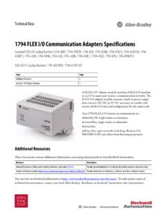
1794-TD014A-EN-P 1794 FLEX I/O ... - Rockwell Automation
literature.rockwellautomation.comSee the Industrial Automation Wiring and Grounding Guidelines, publication 1770-4.1. 1 - on power ports 2 - on communications ports Ethernet connector 1 Ethernet RJ45 Cate gory 5 2 Ethernet RJ45 Category 5 North American temperature code T4A T5 T4A IEC Temp code T4 T5 T4 Terminal screw torque 0.8 Nm (7 lb-in.)