Transcription of 005-037 Fuel Pump Timing - JustAnswer - About Us
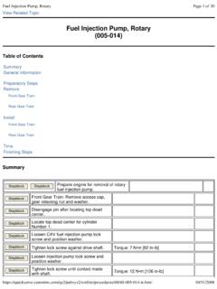
1 View Related Topic 005-037 fuel Pump Timing general InformationPump-to- engine Timing is extremely critical. Pump Timing that is off by only a few crankshaft degrees will cause:Poor performance - starting and fuel TimeEngine pump Timing begins with the Timing of the fuel injection pump drive gear to the camshaft first step is the location of TDC of the compression stroke for cylinder Number , depending on the engine configuration, an alpha character on the injection pump drive gear will possibly need to be aligned with the mark on the camshaft gear. Page 1 of 12 fuel Pump Timing11/4/2010 This table must be used to maintain proper fuel injection pump-to- engine Timing . The Control Parts List (CPL) number from the engine dataplate and the Control Parts List Manual, Bulletin 3379133 or 4021327, must be used to determine whether the engine is certified, and if so, what year and regulating agency (EPA or CARB).
2 Given this information , use the following table to determine which letter on the fuel injection pump drive gear is aligned with the camshaft : Timing mark alignment is not required for the Nippondenso EP-9 or Bosch in-line drive : The Timing mark is not required for Bosch VE and DP210 used on Tier II Industrial engines. For these engines, vary Timing by using the Timing Check on Pump GearEngine ModelInjection , , , CAV DPA pumpAll , VE1986, 1987 EPA, All pre-1986, All , VE1986, 1987 EPA, All pre-1986, All noncertified, CPL , , , CAV DPAAll , VE1986, 1987, 1988, 1989, 1990, 1991, 1992 , VE1986, 1987, 1988, 1989, 1990, 1991, 1992 CARB, 1988, 1989, 1990, 1991, 1992 CAV DPAAll Fire PumpsHNot used at this timeN/AN/APage 2 of 12 fuel Pump Timing11/4/2010 verify that the fuel injection pump is timed correctly, first check the alignment marks on the pump flange and gear : 1 mm of rotation past the Timing mark will advance or retard (depending on direction of rotation) the pump Timing by 1 degree.
3 The Lucas CAV DPA, DPS, Delphi DP210, Stanadyne DB4, and the Bosch VE fuel injection pumps all have a provision for locking the pump shaft at a position corresponding to top dead center for cylinder Number 1. New and reconditioned fuel injection pumps must be received with the shafts located in this position. At the point of injection, the keyway of the shaft will align with the delivery valve receiving the injection and the illustrated hash mark on the seal : The illustrated mark is for reference only and must not be used for setting the fuel injection pump Timing . The Number 1 cylinder delivery valve is marked as cylinder = ASix cylinder = D Page 3 of 12 fuel Pump Timing11/4/2010 OrderFour CylinderSix CylinderA =1D = 1B = 3E = 5C = 4F = 3D = 2A = 6 B = 2 C = 4 The engine is equipped with an engine Timing pin to locate top dead center (TDC) for cylinder Number 1.
4 CAUTION If the Timing pin is incorrectly located on the gear housing, the pump will not be timed precisely locating TDC for cylinder Number 1, the factory positions the Timing pin assembly to the gear housing, using the Timing pin and the hole in the camshaft gear. If the gear housing or Timing pin assembly are removed, the same precision is required to relocate the Timing pin assembly is incorrectly located, reposition the Timing pin. Page 4 of 12 fuel Pump Timing11/4/2010 flange of a replacement pump must be marked to align with the mark on the gear housing after production, after the locked pump is fitted to the engine with cylinder Number 1 at top dead center (TDC), a mark is stamped on the gear housing and the pump flange. Thereafter, when these marks are aligned, the pump is correctly timed to the : The marks on the gear housing and the pump flange are unique to each engine .
5 See Service Tool Instruction, Bulletin 3400196 and Service Tool Catalog, Bulletin 3377710 to determine the appropriate Bosch Timing tool and adapter kit part special indicator can be used to measure the position of the Bosch VE fuel injection pump plunger to check pump Timing . Stanadyne DB4 fuel Injection Pump TimingClean all debris from around the fuel injection pump Timing window cover. Page 5 of 12 fuel Pump Timing11/4/2010 the fuel injection pump Timing cover. Rotate the fuel injection pump driveshaft in the direction of pump rotation to align the Timing line on the weight retainer hub with the line on the cam ring. Position the fuel injection driveshaft locking key plate in the locked position. Turn the locking screw in until contact is made with the Value: [105 in-lb] Verify the Timing marks are aligned after Timing is locked.
6 Page 6 of 12 fuel Pump Timing11/4/2010 Install the fuel injection pump Timing cover. CAV DPA/DPS fuel Injection Pump TimingCorrect Timing of the Lucas CAV DPA/DPS fuel injection pump can be verified by removing the inspection : Special equipment in an authorized shop is required to time the Lucas CAV DPA fuel injection pump precisely. However, for troubleshooting and in an emergency, visual alignment of the Timing mark is close enough for the engine to of these checks are described in the fuel injection pump replacement. Refer to Procedure 005-012 ( fuel Injection pumps , In-Line) in Section 5. Refer to Procedure 005-014 ( fuel Injection Pump, rotary ) in Section 5. Refer to Procedure 005-013 ( fuel Injection Pump, In-Line, Spill Port Timing ) in Section 5 for installation of the Timing pin.
7 Page 7 of 12 fuel Pump Timing11/4/2010 Check - (Bosch VE Pump)Rotate the crankshaft to top dead center (TDC). Remove the plug from the end of the pump. CAUTION Do not bend the fuel lines. Doing so can result in fuel system Service Tool Instruction, Bulletin 3400196 and Service Tool Catalog, Bulletin 3377710 to determine the appropriate Bosch Timing tool and adapter kit part the Timing indicator. Be sure to allow adequate travel for the order to install the Timing indicator, it is often necessary to disconnect one or more of the fuel lines from the fuel : The indicator is marked in increments of mm. 1 revolution of Page 8 of 12 fuel Pump Timing11/4/2010 indicator needle is equal to mm. Bar the crankshaft in the direction opposite engine rotation until the indicator needle stops moving.
8 Adjust the indicator face to read the crankshaft back to top dead center (TDC), and count the number of revolutions of the indicator needle. The reading shown when the engine Timing pin engages is the amount of plunger lift the pump has at that point. Bosch VE pumps with Slotted Mounting HolesRotate the pump on the mounting studs until the indicator reads the correct value for plunger lift. This illustration gives an example of the indicator readings for the various plunger lift the flange mounting Value: 24 [18 ft-lb] Bosch VE pumps with Round Mounting HolesRotate the engine until the plunger travel is at the desired the fuel pump. Refer to Procedure 005-014 ( fuel Injection Pump, rotary ) in Section 5. Page 9 of 12 fuel Pump Timing11/4/2010 the fuel pump drive gear from the pump shaft.
9 Refer to Procedure 005-014 ( fuel Injection Pump, rotary ) in Section 5 With the pump locked, rotate the engine back to TDC. Torque the fuel pump drive nut. Refer to Procedure 005-014 ( fuel Injection Pump, rotary ) in Section 5. Unlock the fuel the correct Timing has been achieved by measuring the static Timing . Remove the Timing indicator. Install the Value: 10 [89 in-lb] Pump Timing - Lucas CAV DPA, Stanadyne DB4, Delphi DP210, Nippondenso EP-9, and Bosch P7100 Rotate the engine to top dead center (TDC). Page 10 of 12 fuel Pump Timing11/4/2010 Correct Timing of the Lucas CAV DPA and Stanadyne DB4 fuel injection pump can be verified by removing the Timing window cover Nippondenso EP-9 and Bosch P-7100 fuel injection pumps are checked by removing the Timing pin access plug and verifying the slot in the pin will fit over the Timing tooth in the fuel injection : Special equipment in an authorized shop is required to time the Lucas CAV DPA fuel injection pump precisely.
10 However, for troubleshooting and in an emergency, visual alignment of the Timing mark is close enough for the engine to correct the Timing on the Bosch P-7100 and Nippondenso EP-9, see the replacement procedure for the respective pump. Two injection pump Timing marks are used on the Stanadyne DB4 for Timing injection of fuel into the Number 1 cylinder. One mark is located on the governor weight retainer hub. The other is located on the internal cam ring. These two marks must be aligned at Number 1 cylinder top dead center (TDC). Page 11 of 12 fuel Pump Timing11/4/2010 the Lucas CAV DPA, the correct Timing letter can be located on the engine dataplate as letter G indicated refers to the correct Timing letter alignment as shown in the previous frame. Last Modified: 22-Jun-2007 Copyright 2000-2010 Cummins Inc.