Transcription of 02'(/ : 96 - M-System
1 MODEL: W2VS. Space-saving Dual Output Signal Conditioners FW: -10 +10 mA DC (Input resistance 100 ). Z: Specify current (See INPUT SPECIFICATIONS). Mini-MW Series Voltage 1: 0 10 mV DC (Input resistance 10 k min.). SIGNAL TRANSMITTER 15: 0 50 mV DC (Input resistance 10 k min.). Functions & Features 16: 0 60 mV DC (Input resistance 10 k min.). Converts DC input from a sensor into a standard process 2: 0 100 mV DC (Input resistance 100 k min.). signal 3: 0 1 V DC (Input resistance 1 M min.). Fast response type available 4: 0 10 V DC (Input resistance 1 M min.). 5: 0 5 V DC (Input resistance 1 M min.). Typical Applications 6: 1 5 V DC (Input resistance 1 M min.). Isolation between control room and field instrumentation 4W: -10 +10 V DC (Input resistance 1 M min.). 5W: -5 +5 V DC (Input resistance 1 M min.). 0: Specify voltage (See INPUT SPECIFICATIONS). ( ). [2] OUTPUT 1. Model Current ( ) A: 4 20 mA DC (Load resistance 750 max.)
2 B: 2 10 mA DC (Load resistance 1500 max.). ZERO C: 1 5 mA DC (Load resistance 3000 max.). SPAN. ZERO 124 D: 0 20 mA DC (Load resistance 750 max.). ( ). E: 0 16 mA DC (Load resistance 900 max.). SPAN. mm (inch). F: 0 10 mA DC (Load resistance 1500 max.). G: 0 1 mA DC (Load resistance 15 k max.). Z: Specify current (See OUTPUT SPECIFICATIONS). MODEL: W2VS [1][2][3]-[4][5] Voltage 1: 0 10 mV DC (Load resistance 10 k min.). 2: 0 100 mV DC (Load resistance 100 k min.). ORDERING INFORMATION. 3: 0 1 V DC (Load resistance 1000 min.). Code number: W2VS-[1][2][3]-[4][5]. 4: 0 10 V DC (Load resistance 10 k min.). Specify a code from below for each [1] through [5]. 5: 0 5 V DC (Load resistance 5000 min.). ( W2VS-6A6-M2/K/CE/Q). 6: 1 5 V DC (Load resistance 5000 min.). Special input and output ranges (For codes Z & 0). 4W: -10 +10 V DC (Load resistance 10 k min.). Specify the specification for option code /Q.
3 5W: -5 +5 V DC (Load resistance 5000 min.). ( /C01/V01). 0: Specify voltage (See OUTPUT SPECIFICATIONS). Note: If one of the outputs should be a current range, specify it for the Output 1 to allow a greater load. [3] OUTPUT 2. Y: None [1] INPUT. Current Current A: 4 20 mA DC (Load resistance 350 max.). A: 4 20 mA DC (Input resistance 250 ). B: 2 10 mA DC (Load resistance 700 max.). A1: 4 20 mA DC (Input resistance 50 ). C: 1 5 mA DC (Load resistance 1400 max.). B: 2 10 mA DC (Input resistance 500 ). D: 0 20 mA DC (Load resistance 350 max.). C: 1 5 mA DC (Input resistance 1000 ). E: 0 16 mA DC(Load resistance 430 max.). D: 0 20 mA DC (Input resistance 50 ). F: 0 10 mA DC (Load resistance 700 max.). E: 0 16 mA DC (Input resistance ). G: 0 1 mA DC (Load resistance 7000 max.). F: 0 10 mA DC (Input resistance 100 ). Z: Specify current (See OUTPUT SPECIFICATIONS). G: 0 1 mA DC (Input resistance 1000 ).
4 Voltage H: 10 50 mA DC (Input resistance 100 ). Same range availability as Output 1. J: 0 10 A DC (Input resistance 1000 ). K: 0 100 A DC (Input resistance 1000 ). GW: -1 +1 mA DC (Input resistance 1000 ). W2VS SPECIFICATIONS ES-5518 Page 1/4. MODEL: W2VS. [4] POWER INPUT INPUT SPECIFICATIONS. AC Power DC Current: M2: 100 240 V AC (Operational voltage range 85 264 V, Shunt resistor attached to the input terminals ( W). 47 66 Hz) Specify input resistance value for code Z. (90 264 V for UL) DC Voltage: -300 +300 V DC. DC Power Minimum span: 3 mV. R: 24 V DC Offset: Max. times span (Operational voltage range 24 V 10 %, ripple 10 %p-p max.) Input resistance R2: 11 27 V DC Span 3 10 mV : 10 k . (Operational voltage range 11 27 V, ripple 10 %p-p max.) Span 10 100 mV : 10 k . (Select /N' for Standards & Approvals' code.) Span 1 V : 100 k . P: 110 V DC Span 1 V : 1 M . (Operational voltage range 85 150 V, ripple 10 %p-p max.)
5 (110 V 10 % for UL). OUTPUT SPECIFICATIONS. DC Current: 0 20 mA DC. [5] OPTIONS (multiple selections) Minimum span: 1 mA. Response Time (0 90 %) Offset: Max. times span blank: Standard ( sec.) Load resistance: Output drive 15 V max. for Output 1;. /K: Fast Response (Approx. 25 msec.) 7 V max. for Output 2. Standards & Approvals (must be specified) DC Voltage: -10 +12 V DC (up to 10 V for Output 2). /N: Without CE or UL Minimum span: 5 mV. /CE: CE marking Offset: Max. times span /UL: UL approval, CE marking Load resistance: Output drive 1 mA max.; at V. Other Options blank: none INSTALLATION. /Q: Option other than the above (specify the specification). Power Consumption (UL not available). AC: Approx. 4 VA at 100 V. SPECIFICATIONS OF OPTION: Q (multiple selections) Approx. 5 VA at 200 V. COATING (For the detail, refer to M-System 's web site.) Approx. 6 VA at 240 V. /C01: Silicone coating DC: Approx.
6 3 W. /C02: Polyurethane coating Operating temperature: -5 to +55 C (23 to 131 F). /C03: Rubber coating Operating humidity: 30 to 90 %RH (non-condensing). ADJUSTMENT Mounting: Surface or DIN rail /V01: Multi-turn fine adjustment Weight: 200 g ( lb). TERMINAL SCREW MATERIAL. /S01: Stainless steel PERFORMANCE in percentage of span Accuracy: %. GENERAL SPECIFICATIONS Temp. coefficient: %/ C ( %/ F). Construction: Plug-in Line voltage effect: % over voltage range Connection: M3 screw terminals (torque N m) Insulation resistance: 100 M with 500 V DC. Screw terminal: Chromated steel (standard) or stainless Dielectric strength: 2000 V AC @1 minute (input to output steel 1 to output 2 to power to ground). Housing material: Flame-resistant resin (black). Isolation: Input to output 1 to output 2 to power STANDARDS & APPROVALS. Overrange output: Approx. -10 to +120 % at 1 5 V. EU conformity: Zero adjustment: -5 to +5 % (front).
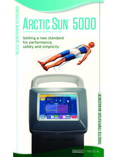
7 EMC Directive Span adjustment: 95 to 105 % (front). EMI EN 61000-6-4. Adjustable individually for each output 1 and output 2. EMS EN 61000-6-2. Low Voltage Directive W2VS SPECIFICATIONS ES-5518 Page 2/4. MODEL: W2VS. EN 61010-1. Installation Category II. Pollution Degree 2. Input or output 1 or output 2 to power input: Reinforced insulation (300 V). Input to output 1 to output 2: Basic insulation (300 V). RoHS Directive EN 50581. Approval: UL/C-UL nonincendive Class I, Division 2, Groups A, B, C, and D. ( , ). UL/C-UL general safety requirements (UL 61010-1, ). DIMENSIONS unit: mm (inch). 6 (.23). DIN RAIL. 35mm wide 3 2 1. 6 5 4. 2 (. ). 59 ( ). 72 ( ). MTG HOLE. ( ). 6 (.24) deep 53 ( ). 11 M3 9 8 7. SCREW 11 10. (.16). 4. 22 (.87). ( ). (.87) 10 (.39) 84 ( ). 114 ( ) [4 (.16)]. When mounting, no extra space is needed between units. TERMINAL ASSIGNMENTS unit: mm (inch). INPUT RESISTOR.
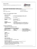
8 (model: REM2). 19 (.75). 3 2 1. 6 5 4. 9 8 7. 11 10. Input shunt resistor attached for current input. W2VS SPECIFICATIONS ES-5518 Page 3/4. MODEL: W2VS. SCHEMATIC CIRCUITRY & CONNECTION DIAGRAM. Isolation Z S. + Low Drift Output *. 1 Amplifier Driver 7 +. INPUT R OUTPUT 1. 2 8 . Z S. 4. Output Driver 3 +. 5 OUTPUT 2. 6 . 9. 10 U(+). POWER. 11 V( ). Base Socket *Input shunt resistor attached for current input. Remark: The section enclosed by broken line is only with 2nd output option. Specifications are subject to change without notice. W2VS SPECIFICATIONS ES-5518 Page 4/4.