Transcription of 02'(/ : 96 - M-System
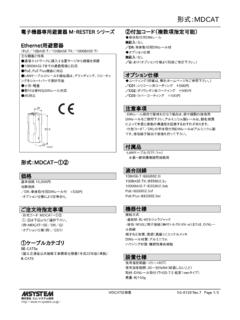
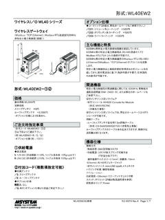
1 MODEL: W5 VSW5VS SPECIFICATIONSES-8513 Page 1/3 Block Dual Output Signal Conditioners W5-UNITSIGNAL TRANSMITTERF unctions & Features Converts a DC input into two isolated outputs Two independent output ranges Four-way isolation (input to output 1 to output 2 to power) Fast response type available High-density mounting45 ( )97( )41 ( )mm (inch)MODEL: W5VS-[1][2][3]-[4][5]ORDERING INFORMATIONS pecify a code from below for each [1] through [5]. Code number: W5VS-[1][2][3]-[4][5] ( W5VS-6A6-R/K/Q) Special input and output ranges (For codes Z, 0, 01 & 02) Specify the specification for option code /Q ( /C01/V01)[1] INPUTC urrentA: 4 20 mA DC (Input resistance 249 )B: 2 10 mA DC (Input resistance 499 )C: 1 5 mA DC (Input resistance 1000 )D: 0 20 mA DC (Input resistance )E: 0 16 mA DC (Input resistance )F: 0 10 mA DC (Input resistance 100 )G: 0 1 mA DC (Input resistance 1000 )H: 10 50 mA DC (Input resistance 20 )Z: Specify current (See INPUT SPECIFICATIONS)Voltage16: 0 60 mV DC (Input resistance 1 M min.)
2 3: 0 1 V DC (Input resistance 1 M min.)4: 0 10 V DC (Input resistance 1 M min.)5: 0 5 V DC (Input resistance 1 M min.)6: 1 5 V DC (Input resistance 1 M min.)4W: -10 +10 V DC (Input resistance 1 M min.)5W: -5 +5 V DC (Input resistance 1 M min.)0: Specify voltage (See INPUT SPECIFICATIONS)(CE not available. Power suffix code M, R2, P only.)01: Specify voltage (See INPUT SPECIFICATIONS)(Choose 01 for CE. Power suffix code R only.)02: Specify voltage (See INPUT SPECIFICATIONS)(CE not available. Power suffix code M, R2, P only.)[2] OUTPUT 1 CurrentA: 4 20 mA DC (Load resistance 550 max.)B: 2 10 mA DC (Load resistance 1100 max.)C: 1 5 mA DC (Load resistance 2200 max.)D: 0 20 mA DC (Load resistance 550 max.)E: 0 16 mA DC (Load resistance 685 max.)F: 0 10 mA DC (Load resistance 1100 max.)
3 G: 0 1 mA DC (Load resistance 11 k max.)Z: Specify current (See OUTPUT SPECIFICATIONS)Voltage1: 0 10 mV DC (Load resistance 10 k min.)2: 0 100 mV DC (Load resistance 100 k min.)3: 0 1 V DC (Load resistance 100 min.)4: 0 10 V DC (Load resistance 1000 min.)5: 0 5 V DC (Load resistance 500 min.)6: 1 5 V DC (Load resistance 500 min.)4W: -10 +10 V DC (Load resistance 2000 min.)5W: -5 +5 V DC (Load resistance 1000 min.)0: Specify voltage (See OUTPUT SPECIFICATIONS)[3] OUTPUT 2 Same range availability as Output 1Y: None[4] POWER INPUTAC PowerM: 85 264 V AC (Operational voltage range 85 264 V,47 66 Hz)(CE not available)DC PowerR: 24 V DC(Operational voltage range 24 V 10 %, ripple 10 %p-p max.)R2: 11 27 V DC(Operational voltage range 11 27 V, ripple 10 %p-p max.)(CE not available)P: 110 V DC(Operational voltage range 85 150 V, ripple 10 %p-p max.)
4 (CE not available)[5] OPTIONS (multiple selections)Response Time (0 90 %)blank: Standard ( sec.)/K: Fast Response (Approx. 25 msec.)Other Optionsblank: noneMODEL: W5 VSW5VS SPECIFICATIONSES-8513 Page 2/3 : Option other than the above (specify the specification)SPECIFICATIONS OF OPTION: Q (multiple selections)COATING (For the detail, refer to M-System 's web site.)/C01: Silicone coating/C02: Polyurethane coating/C03: Rubber coatingADJUSTMENT/V01: Multi-turn fine adjustment/VN: Sealed adjustment holesGENERAL SPECIFICATIONSC onstruction: Terminal blockConnection Input: screw terminals (torque N m) Output & power: M3 screw terminals (torque N m)Screw terminal: Nickel-plated steelHousing material: Flame-resistant resin (black)Isolation: Input to output 1 to output 2 to powerOverrange output: Approx. -10 to +120 % at 1 5 VZero adjustment: -2 to +2 % (front)( 1 % with the input suffix codes 4W and 5W selected)Span adjustment: 98 to 102 % (front)(99 to 101 % with the input suffix codes 4W and 5 Wselected.)
5 INPUT SPECIFICATIONS DC Current: Input resistor incorporatedSpecify input resistance value among followings for code Z. 20 , , , 100 , 249 , 499 , 1000 ( W [Input current]2 R) DC VoltageInput resistance: 1 M min.; 10 k min. for the input code0210 k min. at power loss Input code 0 (Not CE) Voltage range: -300 +300 V DC Minimum span: 100 mV Offset: Max. times span Input code 01 (CE) Voltage range: -70 +70 V DC Minimum span: 100 mV Offset: Max. times span Input code 02 (Not CE) Voltage range: -100 +100 mV DC Minimum span: 5 mV Offset: Max. times spanOUTPUT SPECIFICATIONS DC Current: 0 20 mA DCMinimum span: 1 mAOffset: Max. times spanLoad resistance: Output drive 11 V max. DC Voltage: -10 +12 V DCSpans: Min. 5 mV, max. 20 VOffset: Max. times spanLoad resistance: Output drive 10 mA max.
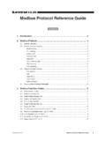
6 ; 5 mA fornegative voltage output; at VINSTALLATION Power Consumption AC: Approx. 4 VA at 100 V Approx. 5 VA at 200 V Approx. 6 VA at 264 V DC: Approx. 3 WOperating temperature: -5 to +55 C (23 to 131 F)Operating humidity: 0 to 90 %RH (non-condensing)Mounting: DIN railWeight: 130 g ( lb)PERFORMANCE in percentage of spanAccuracy: %Temp. coefficient: %/ C ( %/ F)Line voltage effect: % over voltage rangeInsulation resistance: 100 M with 500 V DCDielectric strength:2000 V AC @1 minute (input to output 1 or output 2 topower to ground)1000 V AC @1 minute (output 1 to output 2)STANDARDS & APPROVALSEU conformity:EMC Directive EMI EN 61000-6-4 EMS EN 61000-6-2 RoHS Directive EN 50581 MODEL: W5 VSW5VS SPECIFICATIONSES-8513 Page 3/3 DIMENSIONS & TERMINAL ASSIGNMENTS unit: mm (inch)543211110987694 ( )45 ( )41 ( )[ (.)]
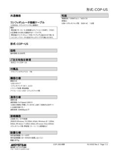
7 13)] When mounting, no extra space is needed between RAIL35mm wide5 (.29)6 M3 SCREW6 (.24)3 (.12)SCHEMATIC CIRCUITRY & CONNECTION DIAGRAM4 Low DriftAmplifier5213U(+)V( )POWER1011+ *Input shunt resistor attached for current 1: The section enclosed by broken line is only with 2nd output 2: DO NOT connect to the terminals 1 2 + OUTPUT 1+ IsolationSZOutputDriverSZOutputDriverOUT PUT 26789*Specifications are subject to change without notice.