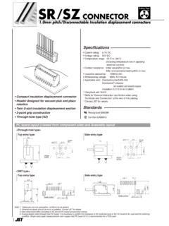
Transcription of 1.0mm pitch/Disconnectable Crimp style connectors
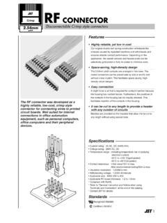
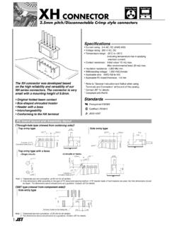
1 Emboss Tape SH CONNECTOR. pitch / disconnectable Crimp style connectors Specifications . Current rating: A AC, DC (AWG #28). 2. 3. Voltage rating: 50 V AC, DC. 4. 5. 6. 7. Temperature range: -25 C to +85 C. 8. 9. 10. 11. (including temperature rise in applying 12. 13. 14. 15. electrical current). Contact resistance: Initial value/ 20 m max. After environmental tests/ 40 m max. Insulation resistance: 100 M min. Withstanding voltage: 500 VAC/minute Applicable wire: Conductor size/ AWG #32 to #28. Insulation to mm * Refer to "General Instruction and Notice when using Terminals and connectors " at the end of this catalog.
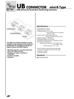
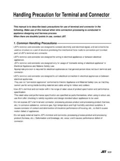
2 * Contact JST for details. The world's first pitch Crimp style * Compliant with RoHS. connector. Compact, low profile design Standards . Compatible with the SR insulation displacement connectors 0 Recognized E60389. Housing lances 1 Certified LR20812. PC board layout and Assembly layout Top entry type Side entry type Header outline 1. 4 1 Header outline Note: 1. The above figure is the figure viewed from the connector mounting side. 2. Tolerances are non-cumulative: mm for all centers. 3. The dimensions above should serve as a guideline.
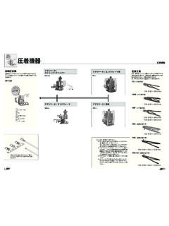
3 Contact JST for details. Contact Applicable wire Q'ty/. Model No. mm2 AWG# Insulation (mm) reel 32 28 23,000. Material and Finish Phosphor bronze, tin-plated (reflow treatment). 2 RoHS compliance Note: Contact JST for gold-plated products. Crimping Applicator Contact machine Crimp applicator Dies Crimp applicator with dies MKS-L-10-3 MK/SSH/L-003-02 APLMK SSH/L003-02. AP-K2N. *MKS-SC SC/SSH/L-003-02 APLSC SSH/L003-02. Note: *Strip- Crimp applicator Contact JST for applicable wires in case that it is not usable due to wire size.
4 1. SH CONNECTOR. Housing Dimensions (mm). With protrusions Circuits Model No. B. Q'ty/. A box B With protrusions Without protrusions With protrusions Without protrusions A 2 SHR-02V-S-B SHR-02V-S 2,000. Circuit 1 3 SHR-03V-S-B SHR-03V-S 2,000. 4 SHR-04V-S-B SHR-04V-S 2,000. 3 2 N 5 SHR-05V-S-B SHR-05V-S 2,000. 6 SHR-06V-S-B SHR-06V-S 2,000. 7 SHR-07V-S-B SHR-07V-S 2,000. 5. 8 SHR-08V-S-B SHR-08V-S 2,000. 9 SHR-09V-S-B SHR-09V-S 2,000. 10 SHR-10V-S-B SHR-10V-S 2,000. 11 SHR-11V-S-B SHR-11V-S 2,000. 12 SHR-12V-S-B SHR-12V-S 2,000.
5 Without protrusions 13 SHR-13V-S-B SHR-13V-S 2,000. 14 SHR-14V-S-B SHR-14V-S 2,000. B. 15 SHR-15V-S-B SHR-15V-S 2,000. A. Circuit 1 20 SHR-20V-S-B 1,000. Material 3 2 N. PBT, UL94V-0, natural (white). RoHS compliance 5. Shrouded header The shrouded headers are interchangeable with those of the SR insulation displacement connectors . Model No. Dimensions (mm) Q'ty/reel Top entry type Circuits Top entry type Side entry type A B Top entry type Side entry type 2 BM02B-SRSS-TB SM02B-SRSS-TB 1,500 3,000. Circuit 3 BM03B-SRSS-TB SM03B-SRSS-TB 1,500 3,000.
6 4 BM04B-SRSS-TB SM04B-SRSS-TB 1,500 3,000. 5 BM05B-SRSS-TB SM05B-SRSS-TB 1,500 3,000. 6 BM06B-SRSS-TB SM06B-SRSS-TB 1,500 3,000. 7 BM07B-SRSS-TB SM07B-SRSS-TB 1,500 3,000. 8 BM08B-SRSS-TB SM08B-SRSS-TB 1,500 3,000. 1 A 9 BM09B-SRSS-TB SM09B-SRSS-TB 1,500 3,000. B 10 BM10B-SRSS-TB SM10B-SRSS-TB 1,500 3,000. 11 BM11B-SRSS-TB SM11B-SRSS-TB 1,500 3,000. 12 BM12B-SRSS-TB SM12B-SRSS-TB 1,500 3,000. Side entry type 13 BM13B-SRSS-TB SM13B-SRSS-TB 1,500 3,000. 14 BM14B-SRSS-TB SM14B-SRSS-TB 1,500 3,000. 15 BM15B-SRSS-TB SM15B-SRSS-TB 1,500 3,000.
7 Circuit 20 SM20B-SRSS-TB 3,000. Material and Finish Contact: Copper alloy, copper-undercoated, tin-plated (reflow treatment). Housing: PA, UL94V-0, natural (ivory). Solder tab: Brass, copper-undercoated, tin-plated (reflow treatment). 1 A RoHS compliance This product displays (LF)(SN) on a label. B Note: 1. The products listed above are supplied on embossed-tape. 2. Contact JST for the headers with gold-plated pins. 3. Contact JST for the top entry type headers with suction cap. 2.