Example: marketing
RF - jst-mfg.com
1 The RF connector was developed as a highly reliable, low-cost, crimp style connector for connecting wires to printed circuit boards. Well suited for internal
Information
Domain:
Source:
Link to this page:
Documents from same domain
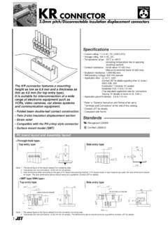
2.0mm pitch/Disconnectable Insulation …
www.jst-mfg.com2 KR CONNECTOR Circuits Model No. Dimensions (mm) Material and Finish Normal type Contact: Phosphor bronze, tin-plated (reflow treatment) …

2.0mm pitch/Disconnectable Crimp style connectors
www.jst-mfg.com2 PHD CONNECTOR Circuits Model No. Dimensions (mm) Q'ty / AB bag Material PA 66, UL94V-0, natural (white) 8 10 12 14 16 18 20 22 24 26 28 30 32 34 PHDR-08VS

CONNECTOR - jst-mfg.com
www.jst-mfg.com3 XH CONNECTOR Top entry type of glass-filled nylon Circuits Model No. Dimensions (mm) Q’ty/ ABbag 2 3 4 5 6 7 8 9 10 11 12 13 14 15 B2B-XH-2 …
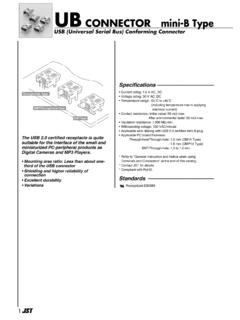
USB (Universal Serial Bus) Conforming Connector
www.jst-mfg.com1 USB (Universal Serial Bus) Conforming Connector UB ラジアル CONNECTOR mini-B Type Specifications ––––––––––––––––––– ...
116 0588 0615 - jst-mfg.com
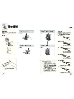
www.jst-mfg.com圧着工具 (注2) 抜き ・ 挿入工具 コンタク ト形番 yrs yc yrm ・ yrf yrk ・ yrk-ex バラ状コンタク ト形番 --- sach-003g-p0.2
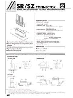
1.0mm pitch/Disconnectable Insulation …
www.jst-mfg.com2 sr/sz connector b 3.6 a 2.45 2.1 1.0 b 2 3 4 5 6 7 8 9 10 11 12 13 14 02sr-3s 03sr-3s 04sr-3s 05sr-3s 06sr-3s 07sr-3s 08sr-3s 09sr-3s 10sr-3s 11sr-3s 12sr-3s 13sr-3s 14sr-3s 2,000 2,000 2,000

Handling Precaution for Terminal and Connector - …
www.jst-mfg.com960 Handling Precaution for Terminal and Connector •When checking circuit of harness with terminal and connector, handling wire harness, etc. in assembly of

CONNECTOR - jst-mfg.com
www.jst-mfg.com1 4.5 2 7.5 15.2 6 4.5 11.7 Tab contact Receptacle contact Tab contact: Phosphor bronze, tin-plated (reflow treatment) Receptacle contact: Copper alloy, tin …
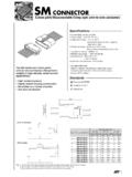
CONNECTOR - jst-mfg.com
www.jst-mfg.com2 SM CONNECTOR Material and Finish Model No. mm2 AWG # Applicable wire Q´ty / reel Pin contact Socket contact SYM-001T-P0.6 0.08 ~0.33 28 22 1.2 1.8 Pin contact: 8,500 Socket contact: 5,000
1.5mm pitch/Disconnectable Insulation …
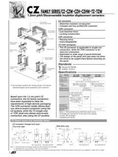
www.jst-mfg.com4 CZ FAMILY SERIES/CZ・CZW・CZH・CZHW・TZ・TZW Line B / Circuit No.1 Line A / Circuit No.1 5.7 0.8 A 0.8 8.1 B H JST Material PBT, …
Related documents
New Models Simulate RF Circuits - Spread spectrum
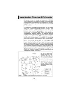
sss-mag.comPage 1 New Models Simulate RF Circuits Its no news to those who simulate that the accuracy of SPICE is directly related to the accuracy of the models.

Bias Circuits for RF Devices - QSL.net
www.qsl.netHighly Stable Active Bias for High Frequency Amplifiers The most common form of biasing in RF circuits is the current mirror. This basic stage is used
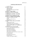
CHAPTER 4 RF/IF CIRCUITS - Mixed-signal and …
www.analog.comRF/IF CIRCUITS INTRODUCTION 4.1 CHAPTER 4: RF/IF CIRCUITS Introduction From cellular phones to 2-way pagers to wireless Internet access, the world is becoming more connected, even though wirelessly.
Create S-Parameter Subcircuits for Microwave and …
www.analog-innovations.comCreate S-Parameter Subcircuits for Microwave and RF Applications 63 Example: AC Analysis of the 10236N S-Parameter Model Figure 24 lists an abridged version of the 10236N subcircuit

Modeling of Integrated RF Passive Devices - …
www.integrandsoftware.comModeling of Integrated RF Passive Devices Sharad Kapur and David E. Long Custom Integrated Circuits Conference, 2010 www.integrandsoftware.com Introduction …
A Simple USB RF Power Meter - Stable32
www.stable32.com2 Figure 2. RF Power Meter Block Diagram Power Meter Circuit Schematics of the RF power meter detector and interface circuits are shown in Figures 3 and 4. It is a
'Single-Supply Op Amp Design Techniques' - TI.com
www.ti.comCircuit Analysis Single-Supply Op Amp Design Techniques 3 The constant requirement to account for inputs connected to ground or other reference voltages makes it difficult to design single-supply op amp circuits.

CHAPTER
www.ik4hdq.net1 CHAPTER Introduction to RF electronics Radio-frequency (RF) electronics differ from other electronics because the higher frequencies make some circuit operation a …
RF MEMS Circuit Design for Wireless Communications
www.ik4hdq.netLibrary of Congress Cataloging-in-Publication Data De Los Santos, HØctor J. RF MEMS circuit design for wireless communications/HØctor J. De Los Santos.