Transcription of CHAPTER 4 RF/IF CIRCUITS - Mixed-signal and …
1 RF/IF CIRCUITS . CHAPTER 4 RF/IF CIRCUITS . INTRODUCTION SECTION : MIXERS THE IDEAL MIXER DIODE-RING MIXER BASIC OPERATION OF THE ACTIVE MIXER REFERENCES SECTION : MODULATORS SECTION : ANALOG MULTIPLIERS REFERENCES SECTION : LOGARITHMIC AMPLIFIERS REFERENCES SECTION : TRUE-POWER DETECTORS SECTION : VARIABLE GAIN AMPLIFIER VOLTAGE CONTROLLED AMPLIFIERS X-AMPS DIGITALLY CONTROLLED VGAs REFERENCES SECTION : DIRECT DIGITAL SYNTHESIS DDS ALIASING IN DDS SYTEMS DDS SYSTEMS AS ADC CLOCK DRIVERS AMPLITUDE MODULATION IN A DDS SYSTEM SPURIOUS FREE DYNAMIC RANGE CONSIDERATIONS REFERENCES SECTION : PHASE-LOCKED LOOPS PLL SYNTHESIZER BASIC BUILDING BLOCKS THE REFERENCE COUNTER THE FEEDBACK COUNTER, N FRACTIONAL-N SYNTHESIZERS NOISE IN OSCILLATOR SYSTEMS PHASE NOISE IN VOLTAGE-CONTROLLED OSCILLATORS LEESON'S EQUATION CLOSING THE LOOP PHASE NOISE MEASUREMENTS REFERENCE SPURS CHARGE PUMP LEAKAGE CURRENTS BASIC LINEAR DESIGN.
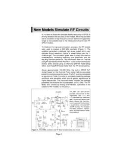
2 SECTION : PHASE-LOCKED LOOPS (cont.). REFERENCES RF/IF CIRCUITS . INTRODUCTION. CHAPTER 4: RF/IF CIRCUITS . Introduction From cellular phones to 2-way pagers to wireless Internet access, the world is becoming more connected, even though wirelessly. No matter the technology, these devices are basically simple radio transceivers (transmitters and receivers). In the vast majority of cases the receivers and transmitters are a variation on the superheterodyne radio shown in Figure for the receiver and Figure for the transmitter. AGC. RF IF DEMOD.
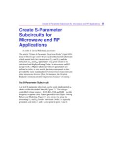
3 LO LO. Figure : Basic Superheterodyne Radio Receiver RF IF MOD. LO LO. Figure : Basic Superheterodyne Radio Transmitter BASIC LINEAR DESIGN. The basic concept of operation is as follows. For the receiver, the signal from the antenna is amplified in the radio frequency (RF) stage. The output of the RF stage is one input of a mixer. A Local Oscillator (LO) is the other input. The output of the mixer is at the Intermediate Frequency (IF). The concept here is that is much easier to build a high gain amplifier string at a narrow frequency band than it is to build a wideband, high gain amplifier.
4 Also, the modulation bandwidth is typically very much smaller than the carrier frequency. A second mixer stage converts the signal to the baseband. The signal is then demodulated (demod). The modulation technique is independent from the receiver technology. The modulation scheme could be amplitude modulation (AM), frequency modulation (FM), phase modulation or some form of quadrature amplitude modulation (QAM), which is a combination of amplitude and phase modulation. To put some numbers around it, let us consider a broadcast FM signal.
5 The carrier frequency is in the range of 98 MHz to 108 MHz. The IF frequency is almost always MHz. The baseband is 0 Hz to 15 kHz. This is the sum of the right and left audio frequencies. There is also a modulation band centered at 38 kHz that is the difference of the left and right audio signals. This difference signal is demodulated and summed with the sum signal to generate the separate left and right audio signals. On the transmit side the mixers convert the frequencies up instead of down. These simplified block diagrams neglect some of the refinements that may be incorporated into these designs, such as power monitoring and control of the transmitter power amplifier as achieved with the True-Power CIRCUITS .
6 As technology has improved, we have seen the proliferation of IF sampling. ADCs of sufficient performance have been developed which allows the sampling of the signal at the IF frequency range, with demodulation occurring in the digital domain. This allows for system simplification by eliminating a mixer stage. In addition to the basic building blocks that are the subject of this CHAPTER , these circuit blocks often appear as building blocks in larger application specific integrated CIRCUITS (ASIC). RF/IF CIRCUITS . MIXER. SECTION : MIXERS.
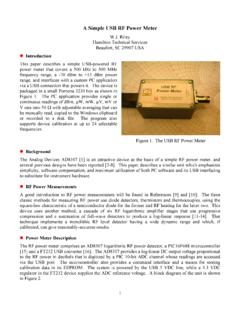
7 The Ideal Mixer An idealized mixer is shown in Figure An RF (or IF) mixer (not to be confused with video and audio mixers) is an active or passive device that converts a signal from one frequency to another. It can either modulate or demodulate a signal. It has three signal connections, which are called ports in the language of radio engineers. These three ports are the radio frequency (RF) input, the local oscillator (LO) input, and the intermediate frequency (IF) output. IDEAL MIXER. RF INPUT IF OUTPUT. fRF fRF + fLO. fRF - fLO. LO INPUT.
8 FLO. Figure : The Mixing Process A mixer takes an RF input signal at a frequency fRF, mixes it with a LO signal at a frequency fLO, and produces an IF output signal that consists of the sum and difference frequencies, fRF fLO. The user provides a bandpass filter that follows the mixer and selects the sum (fRF + fLO) or difference (fRF fLO) frequency. Some points to note about mixers and their terminology: When the sum frequency is used as the IF, the mixer is called an upconverter; when the difference is used, the mixer is called a downconverter.
9 The former is typically used in a transmit channel, the latter in a receive channel. In a receiver, when the LO frequency is below the RF, it is called low-side injection and the mixer a low-side downconverter; when the LO is above the RF, it is called high-side injection, and the mixer a high-side downconverter. BASIC LINEAR DESIGN. Each of the outputs is only half the amplitude (one-quarter the power) of the individual inputs; thus, there is a loss of 6 dB in this ideal linear mixer. (In a practical multiplier, the conversion loss may be greater than 6 dB, depending on the scaling parameters of the device.)
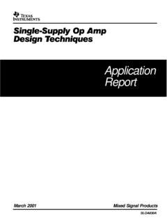
10 Here, we assume a mathematical multiplier, having no dimensional attributes.). A mixer can be implemented in several ways, using active or passive techniques. Ideally, to meet the low noise, high linearity objectives of a mixer we need some circuit that implements a polarity-switching function in response to the LO input. Thus, the mixer can be reduced to Figure , which shows the RF signal being split into in-phase (0 ) and anti-phase (180 ) components; a changeover switch, driven by the local oscillator (LO) signal, alternately selects the in-phase and antiphase signals.