Transcription of CHAPTER
1 Source: Secrets of RF Circuit Design 1. CHAPTER . Introduction to RF. electronics radio - frequency (RF) electronics differ from other electronics because the higher frequencies make some circuit operation a little hard to understand. Stray capacitance and stray inductance afflict these circuits. Stray capacitance is the capacitance that exists between conductors of the circuit, between conductors or components and ground, or between components. Stray inductance is the normal in- ductance of the conductors that connect components, as well as internal component inductances. These stray parameters are not usually important at dc and low ac frequencies, but as the frequency increases, they become a much larger proportion of the total. In some older very high frequency (VHF) TV tuners and VHF communi- cations receiver front ends, the stray capacitances were sufficiently large to tune the circuits, so no actual discrete tuning capacitors were needed.
2 Also, skin effect exists at RF. The term skin effect refers to the fact that ac flows only on the outside portion of the conductor, while dc flows through the entire con- ductor. As frequency increases, skin effect produces a smaller zone of conduction and a correspondingly higher value of ac resistance compared with dc resistance. Another problem with RF circuits is that the signals find it easier to radiate both from the circuit and within the circuit. Thus, coupling effects between elements of the circuit, between the circuit and its environment, and from the environment to the circuit become a lot more critical at RF. Interference and other strange effects are found at RF that are missing in dc circuits and are negligible in most low- frequency ac circuits. The electromagnetic spectrum When an RF electrical signal radiates, it becomes an electromagnetic wave that includes not only radio signals, but also infrared, visible light, ultraviolet light, X-rays, gamma rays, and others.
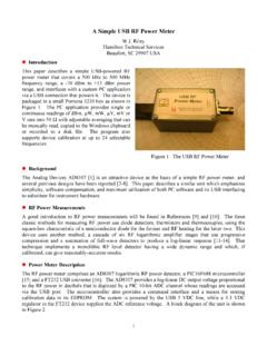
3 Before proceeding with RF electronic circuits, therefore, take a look at the electromagnetic spectrum. 1. Downloaded from Digital Engineering Library @ McGraw-Hill ( ). Copyright 2004 The McGraw-Hill Companies. All rights reserved. Any use is subject to the Terms of Use as given at the website. Introduction to RF electronics 2 Introduction to RF electronics The electromagnetic spectrum (Fig. 1-1) is broken into bands for the sake of convenience and identification. The spectrum extends from the very lowest ac fre- quencies and continues well past visible light frequencies into the X-ray and gamma- ray region. The extremely low frequency (ELF) range includes ac power-line frequencies as well as other low frequencies in the 25- to 100-hertz (Hz) region. The Navy uses these frequencies for submarine communications. 1-1 The electromagnetic spectrum from VLF to X-ray.
4 The RF region covers from less than 100 kHz to 300 GHz. The very low frequency (VLF) region extends from just above the ELF region, although most authorities peg it to frequencies of 10 to 100 kilohertz (kHz). The low- frequency (LF) region runs from 100 to 1000 kHz or 1 megahertz (MHz). The medium-wave (MW) or medium- frequency (MF) region runs from 1 to 3 MHz. The amplitude-modulated (AM) broadcast band (540 to 1630 kHz) spans portions of the LF and MF bands. The high- frequency (HF) region, also called the shortwave bands (SW), runs from 3 to 30 MHz. The VHF band starts at 30 MHz and runs to 300 MHz. This region includes the frequency -modulated (FM) broadcast band, public utilities, some tele- vision stations, aviation, and amateur radio bands. The ultrahigh frequencies (UHF). run from 300 to 900 MHz and include many of the same services as VHF. The mi- crowave region begins above the UHF region, at 900 or 1000 MHz, depending on source authority.
5 You might well ask how microwaves differ from other electromagnetic waves. Microwaves almost become a separate topic in the study of RF circuits because at these frequencies the wavelength approximates the physical size of ordinary elec- tronic components. Thus, components behave differently at microwave frequencies than they do at lower frequencies. At microwave frequencies, a metal film re- sistor, for example, looks like a complex RLC network with distributed L and C val- ues and a surprisingly different R value. These tiniest of distributed components have immense significance at microwave frequencies, even though they can be ig- nored as negligible at lower RFs. Before examining RF theory, first review some background and fundamentals. Units and physical constants In accordance with standard engineering and scientific practice, all units in this book will be in either the CGS (centimeter-gram-second) or MKS (meter- kilogram-second) system unless otherwise specified.
6 Because the metric system de- Downloaded from Digital Engineering Library @ McGraw-Hill ( ). Copyright 2004 The McGraw-Hill Companies. All rights reserved. Any use is subject to the Terms of Use as given at the website. Introduction to RF electronics Units and physical constants 3. pends on using multiplying prefixes on the basic units, a table of common metric prefixes (Table 1-1) is provided. Table 1-2 gives the standard physical units. Table 1-3 gives physical constants of interest in this and other chapters. Table 1-4 gives some common conversion factors. Table 1-1. Metric prefixes Metric prefix Multiplying factor Symbol tera 1012 T. giga 109 G. mega 106 M. kilo 103 K. hecto 102 h deka 10 da deci 10 1 d centi 10 2 c milli 10 3 m micro 10 6 u nano 10 9 n pico 10 12 p femto 10 15 f atto 10 18 a Table 1-2. Units of measure Quantity Unit Symbol Capacitance farad F.
7 Electric charge coulomb Q. Conductance mhos Conductivity mhos/meter /m Current ampere A. Energy joule (watt-second) j Field volts/meter E. Flux linkage weber (volt/second). frequency hertz Hz Inductance henry H. Length meter m Mass gram g Power watt W. Resistance ohm . Time second s Velocity meter/second m/s Electric potential volt V. Downloaded from Digital Engineering Library @ McGraw-Hill ( ). Copyright 2004 The McGraw-Hill Companies. All rights reserved. Any use is subject to the Terms of Use as given at the website. Introduction to RF electronics 4 Introduction to RF electronics Table 1-3. Physical constants Constant Value Symbol Boltzmann's constant 10 23 J/K K. Electric chart (e ) 10 19 C q Electron (volt) 10 19 J eV. Electron (mass) 10 31 kg m Permeability of free space 4 10 7 H/m U0. Permitivity of free space 10 12 F/m 0. Planck's constant 10 34 J-s h Velocity of electromagnetic waves 3 108 m/s c Pi ( ).
8 Table 1-4. Conversion factors 1 inch cm 1 inch mm 1 foot m 1 statute mile km 1 nautical mile 6,080 feet (6,000 feet)a 1 statute mile 5,280 feet 1 mile in 10 5 m 1 kg lb 1 neper dB. 1 gauss 10,000 teslas a Some navigators use 6,000 feet for ease of calculation. The nautical mile is 1/360 of the Earth's circumference at the equator, more or less. Wavelength and frequency For all wave forms, the velocity, wavelength, and frequency are related so that the product of frequency and wavelength is equal to the velocity. For radiowaves, this relationship can be expressed in the following form: l F2 c, (1-1). where wavelength in meters (m). F frequency in hertz (Hz). dielectric constant of the propagation medium c velocity of light (300,000,000 m/s). The dielectric constant ( ) is a property of the medium in which the wave prop- agates. The value of is defined as for a perfect vacuum and very nearly for dry air (typically ).
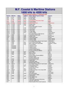
9 In most practical applications, the value of in dry air is taken to be For media other than air or vacuum, however, the velocity of prop- Downloaded from Digital Engineering Library @ McGraw-Hill ( ). Copyright 2004 The McGraw-Hill Companies. All rights reserved. Any use is subject to the Terms of Use as given at the website. Introduction to RF electronics Microwave letter bands 5. agation is slower and the value of relative to a vacuum is higher. Teflon, for exam- ple, can be made with values from about 2 to 11. Equation (1-1) is more commonly expressed in the forms of Eqs. (1-2) and (1-3): c l (1-2). F 2 . and c F . (1-3). l2 . [All terms are as defined for Eq. (1-1).]. Microwave letter bands During World War II, the military began using microwaves in radar and other applications. For security reasons, alphabetic letter designations were adopted for each band in the microwave region.
10 Because the letter designations became in- grained, they are still used throughout industry and the defense establishment. Un- fortunately, some confusion exists because there are at least three systems currently in use: pre-1970 military (Table 1-5), post-1970 military (Table 1-6), and the IEEE. and industry standard (Table 1-7). Additional confusion is created because the mili- tary and defense industry use both pre- and post-1970 designations simultaneously and industry often uses military rather than IEEE designations. The old military des- ignations (Table 1-5) persist as a matter of habit. Skin effect There are three reasons why ordinary lumped constant electronic components do not work well at microwave frequencies. The first, mentioned earlier in this chap- ter, is that component size and lead lengths approximate microwave wavelengths. Table 1-5.