Transcription of A Simple USB RF Power Meter - Stable32
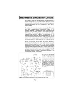
1 1 A Simple USB RF Power Meter Riley Hamilton Technical Services Beaufort, SC 29907 USA Introduction This paper describes a Simple USB-powered RF Power Meter that covers a 500 kHz to 500 MHz frequency range, a -70 dBm to +13 dBm Power range, and interfaces with a custom PC application via a USB connection that powers it. The device is packaged in a small Pomona 3230 box as shown in Figure 1. The PC application provides single or continuous readings of dBm, W, mW, V, mV or V rms into 50 with adjustable averaging that can be manually read, copied to the Windows clipboard or recorded to a disk file. The program also supports device calibration at up to 24 selectable frequencies.
2 Figure 1. The USB RF Power Meter Background The Analog Devices AD8307 [1] is an attractive device as the basis of a Simple RF Power Meter , and several previous designs have been reported [2-8]. This paper describes a similar unit which emphasizes simplicity, software compensation, and maximum utilization of both PC software and its USB interfacing to substitute for instrument hardware. RF Power Measurements A good introduction to RF Power measurements will be found in References [9] and [10]. The three classic methods for measuring RF Power use diode detectors, thermistors and thermocouples, using the square-law characteristic of a semiconductor diode for the former and RF heating for the latter two.
3 This device uses another method, a cascade of six RF logarithmic amplifier stages that use progressive compression and a summation of full-wave detectors to produce a log-linear response [11-14]. That technique implements a monolithic RF level detector having a wide dynamic range and which, if calibrated, can give reasonably-accurate results. Power Meter Description The RF Power Meter comprises an AD8307 logarithmic RF Power detector, a PIC16F688 microcontroller [15] and a FT232 USB converter [16]. The AD8307 provides a log-linear DC output voltage proportional to the RF Power in decibels that is digitized by a PIC 10-bit ADC channel whose readings are accessed via the USB port.
4 The microcontroller also provides a command interface and a means for storing calibration data in its EEPROM. The system is powered by the USB 5 VDC line, while a VDC regulator in the FT232 device supplies the ADC reference voltage. A block diagram of the unit is shown in Figure 2. 2 Figure 2. RF Power Meter Block Diagram Power Meter circuit Schematics of the RF Power Meter detector and interface circuits are shown in Figures 3 and 4. It is a very straightforward application of the three devices used, with no adjustments or frequency compensation since those aspects of the unit s accuracy are handled by calibration. The detector input termination includes a series inductor to provide return loss compensation.
5 The AD8307 is quite insensitive to supply voltage and temperature variations, and the FT232 regulator provides a stable ADC reference at a voltage consistent with good ADC resolution. The four 1/8 Watt 0805 SMT resistors can handle a maximum Power of +27 dBm, but is it reasonable to impose an input Power limit of +20 dBm since useful measurements cannot be made at that level. The input is DC-coupled to these resistors, so no significant DC component should be applied (5V maximum). Figure 3. Detector Section Schematic 3 Figure 4. Interface Section Schematic Board Layout The circuit board layout of the USB RF Power Meter is shown in Figures 5 and 6. It uses the smallest-available surface mount components for the ICs, and fits into a small Pomana box with a soldered connection to the RF input BNC connector at one end and a board-mounted Type-B USB female connector at the other end.
6 Four 0805 resistors are used as the input termination for Power handling, while the ground plane is removed under them to reduce shunt capacitance. Terminals are provided for in- circuit programming of the PIC microcontroller, and there is a test point for measuring the ADC reference voltage. Figure 5. Detector Section PWB Layout Figure 6. Interface Section PWB Layout Power Meter Construction The main consideration is constructing the Power Meter is to use good RF practices at the input so that the unit presents a broadband 50 input impedance. It is also important that the RF detector be well-shielded to avoid stray pickup. 4 A breadboard USB RF Power Meter was constructed by using a PICPROTO 4 [17] prototyping board and a FT232R RS-232 to USB board [18], as shown in Figures 7 and 8.
7 Figure 7. RF Power Meter Breadboard - Closed Figure 8. RF Power Meter Breadboard - Open The final design uses a x Size B Pomona 3230 box [19] with two flange mounting BNC receptacles as a suitable (albeit quite expensive) housing for the USB RF Power Meter , as shown in Figure 9. One BNC connector is used for the RF input, while the other BNC connector is replaced with a Type B female USB connector. The original hole is simply filed square to accommodate the plug on the USB cable, and the USB connector is attached completely inside the box with its pins upward by two 4-40 mounting screws. The paint is scratched away inside of the box where the body of the USB connector contacts the box to assure good grounding.
8 The four original BNC flange mounting holes can be left empty or filled with short 4-40 machine screws. Figure 9. Pomona 3230 Box with Connectors 5 A photograph of the assembled USB RF Power Meter is shown in Figure 10. The detector section is mounted vertically directly behind and facing the input BNC connector and the interface section is mounted upside-down at opposite end of the box, supported by the USB connector. The two sections are connected by three short wires (+5V, signal and ground). The Power and signal leads are filtered by ferrite beads and bypass capacitors on the interface board, and there is no evidence of stray RF pickup.
9 Use of a USB cable with a ferrite bead is recommended to avoid spurious components from the computer. Figure 10. Assembled USB RF Power Meter Calibration Calibration using an RF source with an accurately-known Power output at the frequencies of interest is required to make absolute measurements with the USB RF Power Meter . Two accurate Power levels, , 0 dBm and -10 dBm, are needed at each frequency to determine the slope and intercept of the detector log-linear response. An HP 8640B RF signal generator and an HP 436A RF Power Meter with an HP 8482A Power sensor are ideal for that purpose, and are used for the testing described here.
10 They cover the desired 500 kHz to 500 MHz frequency range, the sensor can measure from +20 dBm to -30 dBm, and the Power Meter has an internal 50 MHz, 0 dBm calibration source. The HP 8640B or another equivalent calibrated signal generator alone is quite sufficient, while the HP 436A or another equivalent 50 MHz Power reference is excellent at that single frequency. Access to those widely-available instruments is needed only for a short time while performing the calibration. The W1 GHZ 50 MHz RF Power standard [20] is low-cost alternative to the HP 436A, but has a rather low -10 dBm nominal output, and the one unit tried here had a Power output that was high by about dB.