Transcription of 1.1 1.2 Antenna Measurements
1 Practical Antennas 1 Antenna Measurements By Michael Hillbun Introduction Friis Equation Traditional Antenna measurement has until recent years required custom techniques and hardware. measurement of small radiated signals over wide dynamic ranges required the use of individually calibrated detectors and low noise high gain receivers. These systems were limited to measurement at a single frequency making frequency sweeps very time consuming. Performing a measurement sweep over Azimuth and Elevation required control and synchronization through the use of a computer. The rapid and unforeseeable evolution of the computer has given Antenna measurement a technological boost.
2 Vector based network analyzers and simple stepper motors are easily controlled by micro computers for large amounts of data collection. Vector based network analyzers also make possible Antenna separation Measurements based on group delay. This chapter will present measurement considerations associated with Antenna Measurements made using fast efficient data collection and processing systems. Far field criteria, reflections and multipath estimates are important knowledge for measurement dynamic range consideration. The choice of Az-EL movement sequencing and its dependence on mechanical considerations and symmetry is presented. Lastly an actual measurement made using a commercially available system is performed using two different techniques one based on use of a calibrated reference and the second based on the 3- Antenna method.
3 Both methods are based on the solution of Friis formula: trtrPGGdP2)4( ( ) Practical Antennas 2 Where: rP = Received power level tP = Transmit power level = Transmit wave length tG = Gain of the transmit Antenna rG = Gain of the transmit Antenna rG = Gain of the receive Antenna d = Separation distance between antennas It is convenient to express Friis formula in terms of S212 = rP/tP and dB: dBrdBtdBLdBGGPS 21 ( ) Where the path loss is defined as: )4(20dLogPdBL ( ) There are several useful measurement constants that can be derived from this simple equation. First note that at a distance of one wavelength from the source the path loss is: )41(20)( ( ) The Path Loss equation can then be written as: )( ( ) Note that each time the distance increases by a factor of 10 the path loss increases 20dB.
4 Similarly if the distance from the source doubles then the Practical Antennas 3 path loss increases by 6dB. These three relationships are summarized as follows: 1. Minimum path loss between any two antennas is -22dB 2. Path loss increases 6dB for each distance factor of 2 from the source 3. Path loss increases 20dB for each distance factor of 10 from the source measurement Estimate Assume a measurement is to be performed using a calibrated horn and a dipole Antenna . The separation distance between the two antennas is to be 200 . The calibrated horn is known to have a gain of 8dB. Estimate the link loss from the above relationships.
5 Solution We know at a distance of one the loss is 22dB and increases 20dB for every separation factor of 10 so at 10 we are at 22dB + 20dB = 42dB and at 100 PL (100 ) = 42dB + 20dB = 62dB. Now at double the distance we encounter an additional 6dB loss resulting in a total path loss of: PL (200 ) = 62 + 6 = 68dB Next add the gain of the horn plus 2dBi for a typical dipole and the link loss estimate is: dBSdB58286821 Practical Antennas 4 Antenna measurement Considerations The measurement of an Antenna under test (AUT) requires knowledge of the desired test field wavefront at the plane of the AUT. If one wishes to perform Measurements on an AUT using a linear yE test field, then tests must be done to insure ),(__zxEY ~ 0 or are acceptably small.
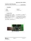
6 Test field energy present in the x,z directions will manifest as a loss and affect the AUT gain. Typically such error components are specified as not to exceed . __YE__XE)(__rEYrAUTL inearly (Y) P olarized Test Antenna Fig 1-1 In this system test field components are required to be linear and constant along the AUT vertical Y axis In measurement systems where the AUT axis is not coincident with the mechanical movement structures axis the AUT will move through the test field in both elevation and separation r . The change in separation will cause a test signal amplitude change.
7 4(20)(rLogrdPdBL ( ) ))(4(20)(rrLogrrdPdBL ( ) Practical Antennas 5 If we define the percentage of d change as rr1then the corresponding increase (or decrease) in test signal level (dB) is: )4(20)4(20)4(20))(4(20rLogrLogrLogrrLogP dBL ( ) )(20 LogPdBL ( ) This equation is a simple expression for path loss change in terms of relative distance. The previous useful relationships can easily be checked. For example is the distance between source Antenna the AUT doubles then, dBLogPanddBL6)2(202 An Antenna measurement system which shifted the AUT toward the source 1% of the separation distance would change the path loss by, dBLogPanddBL087.)
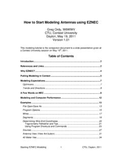
8 99(. Elevation swing rAzimuth rotationdyr =r+drSource Fig 1-2 AUT test setup showing the movement (dx,dy) of the AUT phase center through the radiated test field Practical Antennas 6 When performing a measurement the uncertainty of path length can significantly affect accuracy. As the path length decreases toward a single wavelength the gradient increases. Path loss is defined as: 2)4(rPL For a given range configuration one must consider the sensitivity to path length inaccuracies. If the range were 36in and the test frequency were 1 to 6 GHz then what is the error/in? The path loss slope is: ))4((2322 rrPL at 36in, 1 GHz = at 36in, 6 GHz Or over frequency: A useful sensitivity figure of merit can be derived from the dB path loss slope.)
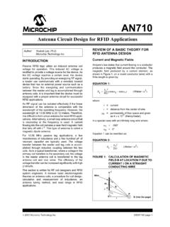
9 Let the db path loss be defined as: )4(20)(rLogrPdBL The path slope of the db path loss is: indbreLogrrPdBL/)(20)( This means the db sensitivity is constant and independent of frequency. If the same plot is performed for 36in and 700 MHz to 6 GHz we have: Practical Antennas 7 Equation is an important and useful parameter. In a typical AUT test setup it is necessary to move either the source or the AUT while making Measurements . Fig 1-3 shows and exaggerated elevation movement of the AUT. The dy movement represents the new vertical position of the AUT in the test field while the dr movement represents the inverse square variation.
10 The two variations give rise to a test field variation dE(r,y) at the AUT phase center. The dr variation caused by inverse square(from the source) is simply)(20 LogPdBL while the dy variation is due to the physical properties of the test field Antenna and must be measured. Diagrammatically the AUT movement looks like: hhrr )cos(1(2 hSourceAUT2 Fig 1-3 The application of the Law of Cosines yields the following simple equation for the source path variation Practical Antennas 8 )2cos())cos(1(22))cos(1(2'222 rhhrr ( ) And )]2cos())cos(1(2))cos(1([21)'(22 rhrhrr ( ) The dB correction factor is then: )]]2cos())cos(1(2))cos(1([21[10)(20 rhrhLogLogPdBL ( ) h/r =.)