Transcription of 1. 2. Government Accession No. - michigan.gov
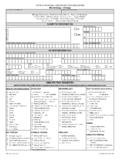
1 ; MDOT Form No. Technical Report Documentation Pa~e 1. Report No. 2. Government Accession No. 3. MDOT Project Manager R-1519 4. Title and Subtitle 5. Report Date Calculating the Critical Buckling Stress for Plates with September 2008 One Free Edge Under Combined Axial and flexural 6. Performing Organization Code Forces 7. Autbor(s) 8. Performing Org. Report No. Rebecca Curtis, , and Roger Till, 9. Performing Organization Name and Address 10. Work Unit No. (TRAlS) michigan Department of Transportation Construction and Technology Division 11.
2 Contract No. Box 30049 Lansing, Ml 48909 ll(a). Authorization No. 12. Sponsoring Agency Name and Address 13. Type of Report & Period Covered michigan Department of Transportation Final Report, 7/08-9/08 Constrution and Technology Division Box 30049 14. Sponsoring Agency Code Lansing, Ml 48909 15. Supplementary Notes 16. Abstract Analysis of gusset plates in truss structures may include checking the combined axial and flexural stresses in a section of the plate. Using concentrically loaded column equations for this analysis provides overly conservative results and may suggest that unnecessary repairs are required.
3 Gusset plates may be treated as plates with the loaded edges supported and the unloaded edges having one edge supported and one edge free. In the review of the literature, formulas and/or buckling coefficients were available for many combinations of plate loading and restraint, but did not include the specific case needed for assessment of gusset plates. Using the energy method and the work of Timoshenko, and Lindquist and Stowell as a basis, equations were developed to find the critical buckling stress for a plate having simply supported loaded edges, a simply supported unloaded edge and a free loaded edge.
4 The equations developed are applicable to rectangular plates with any length to width ratio and also to any combination of linear-varying stress. 18. Distribution Statement critical buckling stress, gusset plate, free edge, No restrictions. This document is combined axial and flexural stress available to the public through the michigan Department of Transportation. 19. Security Classification-report 20. Security Classification-page 21. No. of Pages 22. Price Unclassified Unclassified 27 michigan DEPARTMENT OF TRANSPORTATION MDOT Calculating the Critical Buckling Stress for Plates with One Free Edge Under Combined Axial and flexural Forces Rebecca Curtis, , and Roger Till, Structural Section Construction and Technology Division Research Report R-1519 michigan Transportation Commission Ted B.
5 Wahby, Chairman Linda Miller Atkinson, Vice Chairwoman Maureen Miller Brosnan, Jerrold Jung Steven K. Girard, James S. Scalici Kirk T. Steudle, Director Lansing, michigan September 2008 The information contained in this report was compiled exclusively for the use of the michigan Department of Transportation. Recommendations contained herein are based upon the research data obtained and the expertise of the researchers, and are not necessarily to be construed as Department policy.
6 No material contained herein is to be reproduced-wholly or in part-without the expressed permission of the Engineer of Construction and Technology. ii TABLE OF CONTENTS Background .. 1 Energy 2 Comparison of Energy Method to Tabulated Values .. 9 Comparison of Energy Method to Finite Element 9 Comparison of Energy Method to Finite Element Values for Sample Gusset Plate .. 10 Resistance 14 Summary .. 15 17 18 iii BACKGROUND When checking gusset plates at sections other than at the point of intersection of the chords, eccentricity of the forces may introduce bending forces in the plate.
7 The width of the section tends to be longer than the unbraced length, and so a small eccentricity may produce compressive bending stresses equal to or greater than the pure axial loading. Due to concern over buckling under compression, these combined effects should be evaluated. While evaluating the tragic collapse of I-35W in Minnesota, these combined forces were evaluated by Holt (1) in the Federal Highway Administration (FHWA) Turner-Fairbanks Highway Research Center Report against: 2* ,22 rLpsi Eq.
8 1 where L is the unsupported length and r is the radius of gyration of the member, both in inches. This equation is related to the buckling stress of a column. In contrast to this, the FHWA Bridge Design Guidance No. 1, Load Rating Evaluation of Gusset Plates in Truss Bridges, Parts A and B (2), suggested, in a draft version, that combined axial and bending forces should be evaluated against fy, the yield strength of the material. Upon further investigation, the FHWA Bridge Design Guidance No. 1 was modified to state that gusset plates act as deep members and this check is not required.
9 While it will be shown that the proposed method is conservative, the authors of this report feel that this check will provide assurance to bridge owners that the intent of the historic criteria (see Eq. 1 above) is being met. Upon inspection, a number of differences can be found between the case of a concentrically loaded column and the free body diagram of a gusset plate. In the case of a column, a four sided plate is loaded at opposing edges. These edges may be simple or fixed, and are assumed to be loaded uniformly in compression.
10 The perpendicular edges are free, or unsupported. The stiffness of the plate is generally also uniform across the section. Finally, multiple modes of buckling may form in the column dependent upon the geometric properties of the section. In contrast to the properties of a column discussed above, the section of a gusset plate is not similar to a column. The four sided section is loaded at opposing edges, which may be simple or fixed, but the loading is not uniform due to the eccentric loading.