Transcription of 1. Introduction
1 1. IntroductionIn a survey conducted by BCA in year 2003 involvingabout 10,000 private residential units, water seepagethrough external walls was found to be a commondefect faced by homeowners. The survey findings alsoshowed that the use of single layer brickwall is themost common cause of water seepage through externalwalls. Almost 90% of the water seepage occurredthrough cracks in the plastered brickwalls. In general,water seepage through external walls occurred withinthe first five years of building seepage through the external walls isunacceptable to the occupants. The problem is furthercompounded by Singapore s high humidity andabundant rainfall throughout the year. High windspeeds experienced by high-rise buildings alsoincrease the likelihood of water seepage.
2 Buildingenvelopes must, therefore, be adequately designedand constructed to prevent ingress of are various external wall systems used in thelocal industry, including precast concrete walls, castin-situ reinforced concrete walls, brickwalls, curtainwalls, cladding walls, concrete block walls, to volume constraint, this publication focuses onprecast concrete walls, cast in-situ reinforced concretewalls and plastered brickwalls. It provides industrygood practices to help achieve durable and effectivewaterproofing of the building Design of External GENERALThe ingress of rainwater impinging on external wallsusually occurs though joints and cracks in the a lesser extent, seepage through absorption andpermeation may also occur depending on the materialand thickness of the of external walls is usually achieved byusing suitable materials, providing adequate wallthickness, designing proper construction details, aswell as providing surface rendering and finishes whichserve as barrier against water ingress.
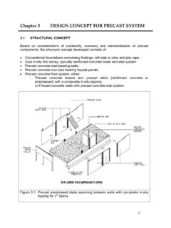
3 Where externalwalls are exposed to severe weather conditions, moreextensive surface waterproofing should be chapter focuses on the design aspects of precastconcrete walls and plastered CHOICE OF EXTERNALWALL SYSTEMThe common types of external walls include cast in-situ reinforced concrete (RC) walls, precast concretewalls and masonry design of external wallsFigure : Common types of external wall systemReinforced Concrete (RC) WallPrecast Concrete WallMasonry BrickwallWater seepage usually occurs through the fabric ofbuilding elements or through the gaps between theseelements. For effective watertightness, the wall systemshould be constructed with impervious material andwith minimal joints. Large precast concrete panelsand cast in-situ RC construction with low water cementratio, in general, have better watertightness performancethan brickwalls, which have extensive joints betweenlayers of bricks.
4 In addition, precast walls have manyother benefits over cast in-situ concrete walls andbrickwalls, such as better quality, higher buildabilityand better , the use of precast concrete walls is stronglyrecommended for external wall EXTERNAL PRECAST WALLSP recast joints are the weakest links in ensuringwatertightness of the external precast concrete include joints between precast concrete elements,between precast and cast in-situ elements, as well asbetween precast elements and window/door framesor other fittings. Joint detailing and the use of suitablesealant should, hence, be carefully considered duringthe design stage. Joints with complicated profiles aredifficult to seal and this may affect the watertightnessof the building are two types of joint detailing employed forprecast concrete walls, namely the one-stage joint andtwo-stage joint.
5 One-stage joint is a simple butt jointwith sealant applied against a backer rod at the externalface of the wall. One-stage joint offers only a singleline of defence against water seepage. Pressure dropmay occur across the one-stage joint and water mayseep through micro cracks or hairline cracks. Two-stage joint (Figure ), on the other hand, providestwo defence lines against water ingress. Experience hasshown that two stage joints give better watertightnessperformance than one-stage of external walls2 Figure : Two-stage joint detailingTwo-stage horizontal joint (Sectional view)Two-stage vertical joint (Plan view) HORIZONTAL JOINTSFor horizontal joints of precast walls, joggled joints(as shown in Figure ) provide better watertightnessperformance than the butt joints.
6 The matchingupstand and downstand profile of the joggled jointprevents inflow of water through the building height of the upstand and downstand is dependenton the exposure conditions, wall thickness and typeof precast wall (load-bearing or non load-bearing). Itgenerally ranges from 35mm for mild exposure to100mm for severe exposure shows the typical details for a horizontaljoggled joint. The joint is sealed with high strengthnon- shrink grout and an approved self-adhesivecompressible waterproofing strip. In addition, anapproved flexible cementitious waterproofingmembrane may be used at the inner corner of theintersection between the wall panel and beam/slabfor enhanced watertightness stripNon- shrink groutINTERNALEXTERNALEXTERNALINTERNALS ealantBacker rodInfill concreteThe gap at the external wall face is usually not sealedto allow incident water in the joint to drain off.
7 If thisgap is also to be sealed (eg. for aesthetic reasons), thejoint can be fully sealed using non- shrink grout, witha backer rod and an appropriate sealant installed atthe exterior end of the joint (Figure ). Alternatively,the joint can be sealed with non- shrink grout at theinterior end with a sealant installed at the exterior endof the joint. For such sealing system, the sealant mustbe discontinued at regular intervals (at intersectionswith the vertical joints) to drain off incident waterthat has managed to seep into the gap (Figure ).For load bearing walls, the entire horizontal jointmust be sealed, for example, with non- shrink grout(Figure ).3design of external wallsFigure : Typical sectional view of horizontal joggled joint (for non load-bearing walls)Approved self-adhesivecompressible waterproofing stripINTERNALEXTERNALHigh strength non- shrink groutApproved flexible cementitiouswaterproofing membrance15mm100mm100mmTypicalstorey levelCast in-situ beamFillet[A][C][B]15mmSlope 1:10 Precast panel[A] 35mm[B] 35mm[B][C] 1design of external walls4 Figure.
8 Typical sectional view of horizontal joggled jointa) Fully sealed horizontal jointb) Sealing of external gap (For non load bearing walls)Joint fully sealed withnon- shrink groutBacker rodSealantApproved self-adhesivecompressible waterproofing stripHigh strengthnon- shrink groutBacker rodSealant must bediscontinued atvertical VERTICAL JOINTSThe two-stage joint detailing is recommended forvertical joints as it provides various water-resistantbarriers. These include a sealant at the outer wall face,a pressure relief space to avoid rain driven penetration,and an infilled concrete/mortar joint with a sealingstrip at the inner wall face. The seal at the external faceshould be discontinued at intersections with thehorizontal joints to allow draining of incident : Vertical joint sealed with sealant and infill concrete/mortar joint, with pressure relief space (plan view)INTERNALEXTERNAL15mm~ 50mmPrecast panelSealantBacker rodPressure relief spaceSealing stripAirtight seal (infill concreteor mortar joint)Figure.
9 Setting back of sealant from the external face of the panel (plan view)For better protection of the sealant from rain, windand UV light, the sealant may be set back from theexternal face of the wall as shown in Figure Thishelps to minimise deterioration of the set back fromexternal faceEXTERNALIf a sealing strip is to be used with the infillconcrete/mortar joint at the inner wall face as shownin Figure , its width should be equal to the jointgap plus sufficient overlap (approximately 60mm) oneach side of the joint. The sealing strip should be madeof an elastic material, or alternatively, some slack inthe sealing strip should be provided so that it doesnot tear under repeated stresses at the joint area.
10 Asuitable gasket can also be used in place of the sealingstrip to create an airtight seal at the inner wall an abutting cast in-situ concrete column orstiffener behind the joint can further enhancewatertightness of the joint. This type of joint is knownas the wet or cast in-situ joint connection, and iseffective in preventing water seepage through theprecast joints. Examples of wet joints are shown inFigure to of external wallsFigure : Dimensions of pressure relief space(plan view)According to CP 81:1999, the grooves that create thepressure relief space should comply with the followingminimum requirements:a)Width = 15mmb)Depth = 5mm; andc)Sharp grooves that create the pressure relief space shouldbe located as shown in Figure below, with thegrooves sloped at an angle not more than 10 fromthe vertical 15mm 5mmGrooveFigure : Typical details of a pressure relief spaceINTERNALEXTERNALG rooveFlashing10 maxdesign of external walls6 Figure : Typical vertical joint with cast in-situ stiffener (plan view)EXTERNALP recast panelsCast in-situ stiffener(or column)Backer rodsSealantPrecast panelsNon- shrink cement groutBars from precast panels(indicative)Figure.