Transcription of 1 Well Testing Analysis - Elsevier.com
1 1 Well y Reser voir Characteristics1 Flow Equations1 Well Testing1 Cur ves1 Derivative Method1 and Pulse Tests1 Well Testing1/1331/2 WELL Testing Primary Reservoir CharacteristicsFlow in porous media is a ver y complex phenomenon andcannot be described as explicitly as flow through pipes orconduits. It is rather easy to measure the length and diam-eter of a pipe and compute its flow capacity as a function ofpressure; however, in porous media flow is different in thatthere are no clear-cut flow paths which lend themselves Analysis of fluid flow in porous media has evolvedthroughout the years along two fronts: the experimental andthe analytical. Physicists, engineers, hydrologists, and thelike have examined experimentally the behavior of variousfluids as they flow through porous media ranging from sandpacks to fused Pyrex glass. On the basis of their analyses,they have attempted to formulate laws and correlations thatcan then be utilized to make analytical predictions for main objective of this chapter is to present the math-ematical relationships that are designed to describe the flowbehavior of the reser voir fluids.
2 The mathematical forms ofthese relationships will var y depending upon the characteris-tics of the reser voir. These primar y reser voir characteristicsthat must be considered include: types of fluids in the reser voir; flow regimes; reser voir geometr y; number of flowing fluids in the reser Types of fluidsThe isothermal compressibility coefficient is essentially thecontrolling factor in identifying the type of the reser voir general, reser voir fluids are classified into three groups:(1) incompressible fluids;(2) slightly compressible fluids;(3) compressible isothermal compressibility coefficientcis describedmathematically by the following two equivalent expressions:In terms of fluid volume:c= 1V V p[ ]In terms of fluid density:c=1 p[ ]whereV=fluid volume =fluid densityp=pressure, psi 1c=isothermal compressibility coefficient, 1 Incompressible fluidsAn incompressible fluid is defined as the fluid whose volumeor density does not change with pressure.
3 That is V p=0and p=0 Incompressible fluids do not exist; however, this behaviormay be assumed in some cases to simplify the derivationand the final form of many flow compressible fluidsThese slightly compressible fluids exhibit small changesin volume, or density, with changes in pressure. Knowing thevolumeVrefof a slightly compressible liquid at a reference(initial) pressurepref, the changes in the volumetric behaviorof this fluid as a function of pressurepcan be mathematicallydescribed by integrating Equation , to give: c pprefdp= VVrefdVVexp[c(pref p)]=VVrefV=Vrefexp[c(pref p)][ ]where:p=pressure, psiaV=volume at pressurep,ft3pref=initial (reference) pressure, psiaVref=fluid volume at initial (reference) pressure, psiaThe exponential exmay be represented by a series expan -sion as:ex=1+x+x22!+x23!+ +xnn![ ]Because the exponentx(which represents the termc(pref p)) is ver y small, the exterm can be approximatedby truncating Equation to:ex=1+x[ ]Combining Equation with gives:V=Vref[1+c(pref p)][ ]A similar derivation is applied to Equation , to give: = ref[1 c(pref p)][ ]where:V=volume at pressurep =density at pressurepVref=volume at initial (reference) pressurepref ref=density at initial (reference) pressureprefIt should be pointed out that crude oil and water systems fitinto this categor fluidsThese are fluids that experience large changes in volume as afunction of pressure.
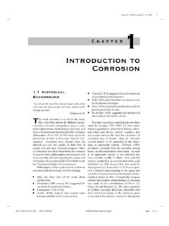
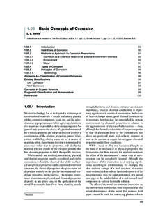
4 All gases are considered compressiblefluids. The truncation of the series expansion as given byEquation is not valid in this categor y and the completeexpansion as given by Equation is isothermal compressibility of any compressible fluidis described by the following expression:cg=1p 1Z Z p T[ ]Figures and show schematic illustrations of the vol-ume and density changes as a function of pressure for thethree types of Flow regimesThere are basically three types of flow regimes that must berecognized in order to describe the fluid flow behavior andreser voir pressure distribution as a function of time. Thesethree flow regimes are:(1) steady-state flow;(2) unsteady-state flow;(3) pseudosteady-state Testing ANALYSIS1/3 PressureCompressibleSlightly CompressibleIncompressibleVolumeFigure volume CompressibleCompressibleFluid Density0 Figure density versus pressure for different fluid flowThe flow regime is identified as a steady-state flow if the pres-sure at ever y location in the reser voir remains constant, ,does not change with time.
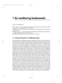
5 Mathematically, this condition isexpressed as: p t i=0[ ]This equation states that the rate of change of pressurepwithrespect to timetat any locationiis zero. In reser voirs, thesteady-state flow condition can only occur when the reser voiris completely recharged and supported by strong aquifer orpressure maintenance flowUnsteady-state flow (frequently called transient flow) isdefined as the fluid flowing condition at which the rate ofchange of pressure with respect to time at any position inthe reser voir is not zero or constant. This definition suggeststhat the pressure derivative with respect to time is essentiallya function of both positioniand timet, thus: p t =f i,t [ ]Pseudosteady-state flowWhen the pressure at different locations in the reser voiris declining linearly as a function of time, , at a con-stant declining rate, the flowing condition is characterizedas pseudosteady-state flow. Mathematically, this definitionstates that the rate of change of pressure with respect totime at ever y position is constant, or: p t i=constant[ ]It should be pointed out that pseudosteady-state flow is com-monly referred to as semisteady-state flow and quasisteady-state shows a schematic comparison of the pressuredeclines as a function of time of the three flow Testing ANALYSISTimeUnsteady-State FlowLocation iSemisteady-State FlowSteady-State FlowPressureFigure ViewPlan ViewFlow LinesFigure radial flow into a Reservoir geometryThe shape of a reser voir has a significant effect on its flowbehavior.
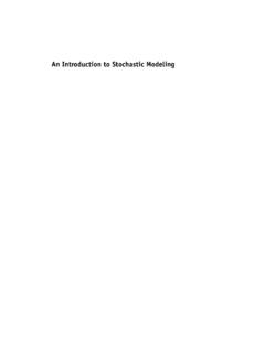
6 Most reser voirs have irregular boundaries anda rigorous mathematical description of their geometr y isoften possible only with the use of numerical , for many engineering purposes, the actual flowgeometr y may be represented by one of the following flowgeometries: radial flow; linear flow; spherical and hemispherical flowIn the absence of severe reser voir heterogeneities, flow intoor away from a wellbore will follow radial flow lines a substan-tial distance from the wellbore. Because fluids move towardthe well from all directions and coverage at the wellbore,the term radial flow is used to characterize the flow of fluidinto the wellbore. Figure shows idealized flow lines andisopotential lines for a radial flow flowLinear flow occurs when flow paths are parallel and the fluidflows in a single direction. In addition, the cross-sectionalWELL Testing ANALYSIS1/5p1p2 AFigure ViewWellPlan ViewFractureFigure linear flow into vertical ViewFlow LinesFigure flow due to limited ViewFlow LinesWellboreFigure flow in a partially of FlowDistancePressurexp1p2 Figure versus distance in a linear to flow must be constant.
7 Figure shows an ideal-ized linear flow system. A common application of linear flowequations is the fluid flow into vertical hydraulic fractures asillustrated in Figure and hemispherical flowDepending upon the type of wellbore completion config-uration, it is possible to have spherical or hemisphericalflow near the wellbore. A well with a limited perforatedinter val could result in spherical flow in the vicinity of theperforations as illustrated in Figure A well which onlypartially penetrates the pay zone, as shown in Figure ,could result in hemispherical flow. The condition could arisewhere coning of bottom water is Number of flowing fluids in the reservoirThe mathematical expressions that are used to predictthe volumetric performance and pressure behavior of areser voir var y in form and complexity depending upon thenumber of mobile fluids in the reser voir. There are generallythree cases of flowing system:(1) single-phase flow (oil, water, or gas);(2) two-phase flow (oil water, oil gas, or gas water);(3) three-phase flow (oil, water, and gas).
8 The description of fluid flow and subsequent Analysis of pres-sure data becomes more difficult as the number of mobilefluids Fluid Flow EquationsThe fluid flow equations that are used to describe the flowbehavior in a reser voir can take many forms depending uponthe combination of variables presented previously ( , typesof flow, types of fluids, etc.). By combining the conser va-tion of mass equation with the transport equation (Darcy sequation) and various equations of state, the necessar y flowequations can be developed. Since all flow equations to beconsidered depend on Darcy s law, it is important to considerthis transport relationship Darcy s lawThe fundamental law of fluid motion in porous media isDarcy s law. The mathematical expression developed byDarcy in 1956 states that the velocity of a homogeneous fluidin a porous medium is proportional to the pressure gradi-ent, and inversely proportional to the fluid viscosity. For ahorizontal linear system, this relationship is:v=qA= k dpdx[ ]vis the apparent velocity in centimeters per second and isequal toq/A, whereqis the volumetric flow rate in cubiccentimeters per second andAis the total cross-sectional areaof the rock in square centimeters.
9 In other words,Aincludesthe area of the rock material as well as the area of the porechannels. The fluid viscosity, , is expressed in centipoiseunits, and the pressure gradient, dp/dx, is in atmospheresper centimeter, taken in the same direction asvandq. Theproportionality constant,k, is the permeability of the rockexpressed in Darcy negative sign in Equation is added because thepressure gradient dp/dxis negative in the direction of flowas shown in Figure Testing ANALYSISrDirection of FlowpwfrwrepeFigure gradient in radial a horizontal-radial system, the pressure gradient ispositive (see Figure ) and Darcy s equation can beexpressed in the following generalized radial form:v=qrAr=k p r r[ ]where:qr=volumetric flow rate at radiusrAr=cross-sectional area to flow at radiusr( p/ r)r=pressure gradient at radiusrv=apparent velocity at radiusrThe cross-sectional area at radiusris essentially the sur-face area of a cylinder. For a fully penetrated well with a netthickness ofh, the cross-sectional areaAris given by:Ar=2 rhDarcy s law applies only when the following conditions exist: laminar (viscous) flow; steady-state flow; incompressible fluids; homogeneous turbulent flow, which occurs at higher velocities, thepressure gradient increases at a greater rate than does theflow rate and a special modification of Darcy s equationis needed.
10 When turbulent flow exists, the application ofDarcy s equation can result in serious errors. Modificationsfor turbulent flow will be discussed later in this Steady-state flowAs defined previously, steady-state flow represents the condi-tion that exists when the pressure throughout the reser voirdoes not change with time. The applications of steady-stateflow to describe the flow behavior of several types of fluid indifferent reser voir geometries are presented below. Theseinclude: linear flow of incompressible fluids; linear flow of slightly compressible fluids; linear flow of compressible fluids; radial flow of incompressible fluids; radial flow of slightly compressible fluids;dxLp1p2 Figure flow model. radial flow of compressible fluids; multiphase flow of incompressible fluidsIn a linear system, it is assumed that the flow occurs througha constant cross-sectional areaA, where both ends areentirely open to flow. It is also assumed that no flow crossesthe sides, top, or bottom as shown in Figure If an incom-pressible fluid is flowing across the element dx, then thefluid velocityvand the flow rateqare constants at all flow behavior in this system can be expressed by thedifferential form of Darcy s equation, , Equation the variables of Equation and integratingover the length of the linear system:qA L0dx= ku p2p1dpwhich results in:q=kA(p1 p2) LIt is desirable to express the above relationship in customar yfield units, or:q=0.