Transcription of 10 CHAPTER 10: STAIRCASES - Islamic University of Gaza
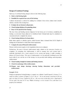
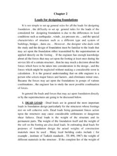
1 1. 10 CHAPTER 10: STAIRCASES . Introduction STAIRCASES provide means of movement from one floor to another in a structure. STAIRCASES consist of a number of steps with landings at suitable intervals to provide comfort and safety for the users. Some common types of stairs are shown in Figure These include straight-flight stairs, quarter-turn stairs, half-turn stairs, branching stairs, and geometrical stairs. (a) (b) (c). (d) (e). (f) (g). 2. (h) (i) (j). Figure : (a); (b) Straight flight stairs; (c) Quarter-turn stairs; (d). Half-turn stairs; (e) Branching stairs; (f) Open-well (half turn); (g). Open-well with quarter turn landing ; (h); (i); (j) Geometrical stairs Technical Terms The definitions of some technical terms, which are used in connection with design of stairs, are given. a. Tread or Going: horizontal upper portion of a step. b. Riser: vertical portion of a step. c. Rise: vertical distance between two consecutive treads. d. Flight: a series of steps provided between two landings.
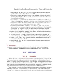
2 E. landing : a horizontal slab provided between two flights. f. Waist: the least thickness of a stair slab. g. Winder: radiating or angular tapering steps. h. Soffit: the bottom surface of a stair slab. i. Nosing: the intersection of the tread and the riser. j. Headroom: the vertical distance from a line connecting the nosings of all treads and the soffit above. Figure shows main technical terms associated with stairs design. 3. Figure : Stairs main technical terms Types of Stairs For purpose of design, stairs are classified into two types; transversely, and longitudinally supported. a- Transversely supported (transverse to the direction of movement): Transversely supported stairs include: Simply supported steps supported by two walls or beams or a combination of both. Steps cantilevering from a wall or a beam. Stairs cantilevering from a central spine beam. b- Longitudinally supported (in the direction of movement): These stairs span between supports at the top and bottom of a flight and unsupported at the sides.
3 Longitudinally supported stairs may be supported in any of the following manners: a. Beams or walls at the outside edges of the landings. b. Internal beams at the ends of the flight in addition to beams or walls at the outside edges of the landings. c. Landings which are supported by beams or walls running in the longitudinal direction. d. A combination of (a) or (b), and (c). e. Stairs with quarter landings associated with open-well stairs. 4. Design of Stairs Simply Supported Figure shows a stair, simply supported on reinforced concrete walls. Figure : Simply supported stairs The waist is chosen to accommodate the reinforcement using appropriate concrete cover. A. waist t of cm is reasonable for this type of stair. Loading: a. Dead load: The dead load includes own weight of the step, own weight of the waist slab, and surface finishes on the steps and on the soffit. b. Live Load: Live load is taken as building design live load plus 150 kg/m2, with a maximum value of 500.
4 Kg/m2. 5. Design for Shear and Flexure: Each step is designed for shear and flexure. Main reinforcement runs in the transverse direction at the bottom side of the steps while shrinkage reinforcement runs at the bottom side of the slab in the longitudinal direction. Since the step is not rectangular, an equivalent rectangular section can be used with an average height equals to t R. havg = +. cos 2. Example ( ): Design a straight flight staircase in a residential building that is supported on reinforced concrete walls m apart (center-to-center) on both sides and carries a live load of 300 kg/m2. The risers are 16 cm and goings are 30 cm. Goings are provided with 3 cm thick marble finish while 2 cm thick plaster is applied to both the risers and bottom surfaces of the slab. Use fc = 250 kg/cm2 , f y = 4200 kg/cm2 , plaster = t/m3 , and marble = t/m3 . Solution: Minimum stair thickness required to satisfy deflection requirements is given by l 150.
5 Hmin = = = cm 20 20. Let slab waist t be equal to cm. Average step height is given as havg = 8 + =8+ = cm > cm cos Loading: a. Dead load: Own weight of step = ( ) ( ) ( ) = t/m of step Own weight of slab = ( ) ( ) ( ) = t/m of step Weight of marble finish = ( ) ( ) ( ) = t/m of step Weight of plaster finish = ( ) ( + ) ( ) = t/m of step b. Live load: Live load = ( ) ( ) = t/m of step 6. c. Factored load: wu = ( + + + ) + ( ) = t/m of step Shear Force: ( ). Vu ,max = = t 2. d = = cm Vc = ( ) 250 (30 )( ) / 1000 = t > t step thickness is adequate for resisting beam shear without using shear reinforcement. Bending Moment: ( )2. M u , max = = t .m 8. Flexural reinforcement ratio is given by (250 ) (10 )5 ( ) . = 1 1 = 4200 . 0 . 9 (30 )(13 .9 )2. (250 ) .. As = As min = (30 )( ) = cm2 /step Use 1 12 mm for each step. For shrinkage reinforcement, As = (100)( ) = cm2 /m Use 1 8 mm @ 30 cm in the longitudinal direction. Figure shows provided reinforcement details.
6 7. Figure : Reinforcement details Cantilever Stairs Figure shows a stairs cantilevered from a reinforced concrete wall. The waist is chosen to accommodate the reinforcement using appropriate concrete cover. A waist t of cm is reasonable for this type of stairs. 8. Figure : Cantilever stairs Loading: a. Dead load: The dead load includes own weight of the step, own weight of the waist slab, surface finishes on the steps and on the soffit, in addition to a concentrated dead load of 100 kg on each step, applied at its free end. b. Live Load: Live load is taken as building design live load plus 150 kg/m2 with a maximum value of 500. kg/m2. Design for Shear and Flexure: Each step is designed for shear and flexure. Main reinforcement runs in the transverse direction at the top side of the steps, while shrinkage reinforcement runs at the bottom side of the slab in the transverse and longitudinal directions. To hold the top reinforcement in position 6 mm stirrups are used every 20 to 25 cm.
7 9. Example ( ): Redesign the stair shown in Example ( ) if it is a cantilever type of a clear span of m. Solution: Minimum stair thickness required to satisfy deflection requirements is given by l 160. hmin = = = cm 10 10. Let slab waist t be equal to cm. Average step height is given as havg = 8 + =8+ = cm > cm cos Shear Force: Vu , max = ( ) + ( ) = t d = = cm Vc = ( ) 250 (30 )( ) / 1000 = > t step thickness is adequate for resisting beam shear without using shear reinforcement. Bending Moment: ( )2. M u , max = + ( )( ) = t .m 2. Flexural reinforcement ratio is given by (250 ) (10 )5 ( ) . = 1 1 = As = (30 )( ) = cm2 / step 4200 . (30 )( ) (250 ) . 2. Use 2 10 mm for each step. For shrinkage reinforcement, As = (100 )( ) = cm2 / m Use 1 8 mm @ 30 cm in both directions. Figure shows details of provided reinforcement. 10. Figure : Reinforcement details Longitudinally-Supported Stairs This type of stairs is designed as one-way slab supported at the top and bottom of the flight, while the steps themselves are treated as nonstructural elements.
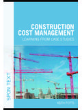
8 Figure shows a half-turn longitudinally supported stairs. Figure : Longitudinally supported stairs Deflection Requirement: Since a flight of stairs is stiffer than a slab of thickness equal to the waist t, minimum required slab depth is reduced by 15 %. Effective Span: The effective span is taken as the horizontal distance between centerlines of supporting elements. 11. Loading: a. Dead Load: The dead load, which can be calculated on horizontal plan, includes: Own weight of the steps. Own weight of the slab. For flight load calculations, this load is to be increased by dividing it by cos to get it on horizontal projection, where is the angle of slope of the flight. Surface finishes on the flight and on the landings. For flight load calculations, the part of load acting on slope is to be increased by dividing it by cos to get it on horizontal projection. b. Live Load: Live load is always given on horizontal projection. Design for Shear and Flexure: The stairs slab is designed for maximum shear and flexure.
9 Main reinforcement runs in the longitudinal direction, while shrinkage reinforcement runs in the transverse direction. Special attention has to be paid to reinforcement detail at opening joints, as shown in Figure Figure : Opening and closing joints Example ( ): Design the staircase shown in Figure The risers are 15 cm and goings are 25 cm, and story height is m. Goings are provided with 3cm-thick marble finish on cement mortar that weighs 120 kg/m2, while 2 cm thick plaster is applied to both the risers and bottom surfaces of 12. the slab. The landings are surface finished with terrazzo tiles on sand filling that weighs 160. kg/m2 . The stair is to be designed for a live load of 300 kg/m2. Use f c = 250 kg / cm 2 , f y = 4200 kg / cm 2 , and plaster = t / m3 . Figure : Longitudinally supported stairs Solution: Minimum stair thickness required to satisfy deflection requirements is given by 480 . hmin = = cm 20 . Let slab waist t be equal to cm.
10 Loading (flight): a. Dead load: Own weight of step = ( ) ( ) = t/m2. Own weight of slab = ( ) ( ) / = t/m2. Weight of marble finish = t/m2. 13. Weight of plaster finish = ( ) ( ) / = t/m2. b. Live load: Live load = t/m2. c. Factored load: wu = ( + + + ) + ( ) = t / m2. wu = ( ) = t / m Loading ( landing ): a. Dead load: Own weight of slab = ( ) ( ) = t/m2. Weight of terrazzo finish = t/m2. Weight of plaster finish = ( ) ( ) = t/m2. b. Live load: Live load = t/m2. c. Factored load: wu = ( + + ) + ( ) = t / m2. wu = ( ) = t / m Shear Force: . Vu ,max = ( ) + = t 2 . d = = cm Vc = ( ) 250 (115 )( ) / 1000 = t > t slab thickness is adequate for resisting beam shear without using shear reinforcement. Bending Moment: 14. Figure : Bending moment diagram M u , max = t .m as shown in Figure Flexural reinforcement ratio is given by (250 ) (10 )5 ( ) . = 1 1 = 4200 . 0 .9 (115 )(18 . 3 )2. (250 ) .. As = (115 )( ) = cm2. Use 8 12 mm . For shrinkage reinforcement, As = (100)(21) = cm2 /m Use 1 8 mm @ 10 cm in the transverse direction.