Transcription of 10. ENERGY EFFICIENT TECHNOLOGIES IN ELECTRICAL SYSTEMS
1 10. ENERGY EFFICIENT TECHNOLOGIES INELECTRICAL SYSTEMS179 Bureau of ENERGY EfficiencySyllabusEnergy EFFICIENT TECHNOLOGIES in ELECTRICAL SYSTEMS :Maximum demand controllers,Automatic power factor controllers, ENERGY EFFICIENT motors, Soft starters with energysaver, Variable speed drives, ENERGY EFFICIENT transformers, Electronic ballast,Occupancy sensors, ENERGY EFFICIENT lighting controls, ENERGY saving potential of Maximum Demand ControllersHigh-tension (HT) consumers have to pay a maximum demand charge in addition to the usualcharge for the number of units consumed. This charge is usually based on the highest amountof power used during some period (say 30 minutes) during the metering month. The maximumdemand charge often represents a large proportion of the total bill and may be based on onlyone isolated 30 minute episode of high power use.
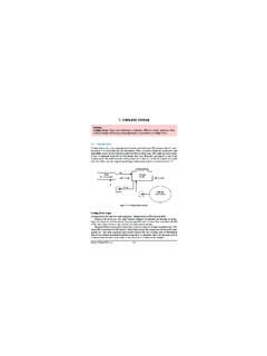
2 Considerable savings can be realised by monitoring power use and turning off or reduc-ing non-essential loadsduring such periods of high power use. Maximum DemandController (See )is a device designed to meetthe need of industries con-scious of the value of loadmanagement. Alarm issounded when demandapproaches a preset value. Ifcorrective action is nottaken, the controller switch-es off non-essential loads ina logical sequence. Thissequence is predeterminedby the user and is pro-grammed jointly by the userand the supplier of thedevice. The plant equip-ments selected for the loadmanagement are stoppedand restarted as per thedesired load profile. Demand control scheme is implemented by using suitable control contac-tors.
3 Audio and visual annunciations could also be used. Figure Maximum Demand Automatic power Factor ControllersVarious types of automatic power factor controls are available with relay / microprocessorlogic. Two of the most common controls are: Voltage Control and kVAr ControlVoltage ControlVoltage alone can be used as a source of intelligence when the switched capacitors areapplied at point where the circuit voltage decreases as circuit load increases. Generally, wherethey are applied the voltage should decrease as circuit load increases and the drop in voltageshould be around 4 5 % with increasing is the most common type of intelligence used in substation applications, whenmaintaining a particular voltage is of prime importance.
4 This type of control is independent ofload cycle. During light load time and low source voltage, this may give leading PF at the sub-station, which is to be taken note ControlKilovar sensitive controls (seeFigure ) are used at loca-tions where the voltage level isclosely regulated and not avail-able as a control variable. Thecapacitors can be switched torespond to a decreasing powerfactor as a result of change insystem loading. This type ofcontrol can also be used to avoidpenalty on low power factor byadding capacitors in steps as thesystem power factor begins tolag behind the desired control requires twoinputs - current and voltage fromthe incoming feeder, which arefed to the PF correction mecha-nism, either the microprocessoror the power Factor Control RelayIt controls the power factor of the installation by giving signals to switch on or off power fac-tor correction capacitors.
5 Relay is the brain of control circuit and needs contactors of appropri-ate rating for switching on/off the is a built-in power factor transducer, which measures the power factor of the installation and converts it to a DC voltage of appropriate polarity. This is compared witha reference voltage, which can be set by means of a knob calibrated in terms of power ENERGY EFFICIENT TECHNOLOGIES in ELECTRICAL System180 Bureau of ENERGY EfficiencyFigure the power factor falls below setting, the capacitors are switched on in sequence. Therelays are provided with First in First out (FIFO) and First in Last Out (FILO) sequence. Thecapacitors controlled by the relay must be of the same rating and they are switched on/off in lin-ear sequence. To prevent over correction hunting, a dead band is provided.
6 This setting deter-mines the range of phase angle over which the relay does not respond; only when the PF goesbeyond this range, the relay acts. When the load is low, the effect of the capacitors is more pro-nounced and may lead to hunting. Under current blocking (low current cut out) shuts off therelay, switching off all capacitors one by one in sequence, when load current is below timing sequences ensure that capacitors are fully discharged before they are switchedin. This avoids dangerous over voltage transient. The solid state indicating lamps (LEDS) dis-play various functions that the operator should know and also and indicate each capacitorswitching power Factor Controller (IPFC)This controller determines the rating of capacitance connected in each step during the first hourof its operation and stores them in memory.
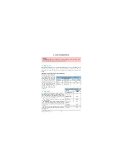
7 Based on this measurement, the IPFC switches onthe most appropriate steps, thus eliminating the hunting problems normally associated withcapacitor ENERGY EFFICIENT Motors Minimising Watts Loss in MotorsImprovements in motor efficiency can beachieved without compromising motor per-formance - at higher cost - within the limitsof existing design and manufacturing tech-nology. From the Table , it can be seen thatany improvement in motor efficiency mustresult from reducing the Watts losses. Interms of the existing state of electric motortechnology, a reduction in watts losses can beachieved in various ways. All of these changes to reduce motorlosses are possible with existing motordesign and manufacturing would, however, require addi-tional materials and/or the use of higherquality materials and improved manufacturing processes resulting in increased motor Stated: REDUCED LOSSES = IMPROVED EFFICIENCY10.
8 ENERGY EFFICIENT TECHNOLOGIES in ELECTRICAL System181 Bureau of ENERGY EfficiencyFigure ENERGY EFFICIENT MotorThus ENERGY - EFFICIENT electric motorsreduce ENERGY losses through improveddesign, better materials, and improved manu-facturing techniques. Replacing a motor maybe justifiable solely on the electricity costsavings derived from an ENERGY -efficientreplacement. This is true if the motor runscontinuously, power rates are high, the motoris oversized for the application, or its nomi-nal efficiency has been reduced by damage orprevious rewinds. Efficiency comparison forstandard and high efficiency motors is shownin Figure aspects of ENERGY EfficientMotorsEnergy- EFFICIENT motors last longer,andmay require less maintenance. At lower temperatures, bearing grease lasts longer; required time between re-greasing increases.
9 Lower temperatures translate to long lasting insulation. Generally, motor life doubles for each 10 C reduction in ENERGY - EFFICIENT motorswith a service factor, and design for operation at 85% ofthe rated motor power problems,especially poor incoming power quality can affect the operationof ENERGY - EFFICIENT motors. 10. ENERGY EFFICIENT TECHNOLOGIES in ELECTRICAL System182 Bureau of ENERGY EfficiencyTABLE WATT LOSS AREA AND EFFICIENCY IMPROVEMENTW atts Loss Area Efficiency Improvement 1. Iron Use of thinner gauge, lower loss core steel reduces eddy current losses. Longercore adds more steel to the design, which reduces losses due to lower operatingflux densities. 2. Stator I2R Use of more copper and larger conductors increases cross sectional area of stator windings.
10 This lowers resistance (R) of the windings and reduces losses due to current flow (I). 3. Rotor I2R Use of larger rotor conductor bars increases size of cross section, lowering conductor resistance (R) and losses due to current flow (I). 4. Friction & Windage Use of low loss fan design reduces losses due to air movement. 5. Stray Load Loss Use of optimised design and strict quality control procedures minimizes stray load Efficiency Range for Standard andHigh Efficiency MotorsSpeed controlis crucial in some applications. In polyphase induction motors, slip is a measureof motor winding losses. The lower the slip, the higher the efficiency. Less slippage in energyefficient motors results in speeds about 1% faster than in standard counterparts. Starting torque for EFFICIENT motors may be lower than for standard motors.