Transcription of 3. ENERGY PERFORMANCE ASSESSMENT OF …
1 3. ENERGY PERFORMANCE ASSESSMENT OFCOGENERATION AND TURBINES (GAS, STEAM)45 Bureau of ENERGY IntroductionCogeneration systems can be broadly classified as those using steam turbines, Gas turbines andDG sets. Steam turbine cogeneration systems involve different types of configurations withrespect to mode of power generation such as extraction, back pressure or a combination of back-pressure, extraction and condensing. Gas turbines with heat recovery steam generators is another mode of on power and steam load variations in the plant the entire system is dynamic. A per-formance ASSESSMENT would yield valuable insights into cogeneration system PERFORMANCE andneed for further Purpose of the PERFORMANCE TestThe purpose of the cogeneration plant PERFORMANCE test is to determine the power output andplant heat rate.
2 In certain cases, the efficiency of individual components like steam turbine isaddressed specifically where PERFORMANCE deterioration is suspected. In general, the plant per-formance will be compared with the base line values arrived at for the plant operating condi-tion rather than the design values. The other purpose of the PERFORMANCE test is to show themaintenance accomplishment after a major overhaul. In some cases the purpose of evaluationcould even be for a total plant PERFORMANCE Terms and Definitions3. ENERGY PERFORMANCE ASSESSMENT of cogeneration and turbine 46 Bureau of ENERGY Reference standardsModern power station practices by British electricity International (Pergamon Press) ASMEPTC 22 - Gas turbine PERFORMANCE Field testing ProcedureThe test procedure for each cogeneration plant will be developed individually taking into con-sideration the plant configuration, instrumentation and plant operating conditions.
3 A method iskCal/kgkCal/kgoutlined in the following section for the measurement of heat rate and efficiency of a co-generation plant. This part provides PERFORMANCE - testing procedure for a coal fired steambased co-generation plant, which is common in Indian Test DurationThe test duration is site specific and in a continuous process industry, 8-hour test data shouldgive reasonably reliable data. In case of an industry with fluctuating electrical/steam load pro-file a set 24-hour data sampling for a representative period. Measurements and Data CollectionThe suggested instrumentation (online/ field instruments) for the PERFORMANCE measurement isas under:Steam flow measurement: Orifice flow metersFuel flow measurements: Volumetric measurements / Mass flow metersAir flow / Flue gas flow: Venturi / Orifice flow meter / Ion gun / Pitot tubesFlue gas Analysis: Zirconium Probe Oxygen analyserUnburnt Analysis: Gravimetric AnalysisTemperature: ThermocoupleCooling water flow: Orifice flow meter / weir /channel flow/ non-contact flow metersPressure : Bourdon Pressure GaugesPower: Trivector meter / ENERGY meterCondensate.
4 Orifice flow meterIt is essential to ensure that the data is collected during steady state plant running others the following are essential details to be collected for cogeneration plant perfor-mance ENERGY PERFORMANCE ASSESSMENT of cogeneration and turbine 47 Bureau of ENERGY EfficiencyStep 1 :Calculate the actualheat extraction in turbine at each stage,Steam Enthalpy at turbine inlet:h1kCal / kg Steam Enthalpy at 1stextraction:h2kCal / kgSteam Enthalpy at 2ndextraction:h3kCal / kg Steam Enthalpy at Condenser:h4*kCal / kg * Due to wetness of steam in the condensing stage, the enthalpy of steam cannot be consideredas equivalent to saturated steam. Typical dryness value is This dryness value can beused as first approximation to estimate heat drop in the last stage.
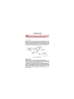
5 However it is suggested to cal-culate the last stage efficiency from the overall turbine efficiency and other stage Electrical ENERGY :1. Total power generation for the trial period from individual Hourly average power generation3. Quantity of power import from utility ( Grid )*4. Quantity of power generation from DG sets.*5. Auxiliaries power consumption* Necessary only when overall cogeneration plant adequacy and system optimization / upgra-dation are the objectives of the Calculations for Steam turbine cogeneration SystemThe process flow diagram for cogeneration plant is shown in figure The following calcu-lation procedures have been provided in this section. turbine cylinder efficiency.
6 Overall plant heat rate3. ENERGY PERFORMANCE ASSESSMENT of cogeneration and turbine 48 Bureau of ENERGY EfficiencyFigure Process Flow Diagram for cogeneration Plant3. ENERGY PERFORMANCE ASSESSMENT of cogeneration and turbine 49 Bureau of ENERGY EfficiencyHeat extraction from inlet:h1 h2kCal / kgto stage 1 extraction (h5)Heat extraction from :h2 h3kCal / kg1st 2ndextraction (h6)Heat extraction from 2nd:h3 h4kCal / kgExtraction condenser (h7)Step 2: From Mollier diagram (H-S Diagram) estimate the theoretical heat extraction for the conditionsmentioned in Step 1. Towards this:a) Plot the turbine inlet condition point in the Mollier chart - corresponding to steampressure and ) Since expansion in turbine is an adiabatic process, the entropy is constant.
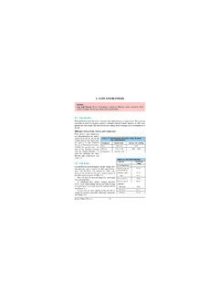
7 Hence drawa vertical line from inlet point (parallel to y-axis) upto the condensing ) Read the enthalpy at points where the extraction and condensing pressure lines meetthe vertical line ) Compute the theoretical heat drop for different stages of Enthalpy after 1stextraction: H1 Theoretical Enthalpy after 2ndextraction: H2 Theoretical Enthalpy at condenser conditionsH3 Theoretical heat extraction from inlet to : h1 H1stage 1 extraction, h8 Theoretical heat extraction from: H1 H21st 2ndextraction, h9 Theoretical heat extraction from: H2 H32ndextraction condensation, h10 Step 3 : Step 4 : Calculate plant heat rate* M x (h1 h11)Heat rate, kCal / kWh=PM Mass flow rate of steam in kg/hrh1 Enthalpy of inlet steam in kCal/kgh11 Enthalpy of feed water in kCal/kgP Average power generated in kW*Alternatively the following guiding parameter can be utilised Plant heat consumption = fuel consumed for power generation, kg/hrPower generated, Example Small cogeneration PlantA distillery plant having an average production of 40 kilolitres of ethanol is having a cogener-ation system with a backpressure turbine .
8 The plant steam and electrical demand are and 100 kW. The process flow diagram is shown in figure calorific value ofIndian coal is 4000kCal/kg3. ENERGY PERFORMANCE ASSESSMENT of cogeneration and turbine 50 Bureau of ENERGY EfficiencyFigure Process Flow Diagram for Small cogeneration Plant Calculations :Step 1 :Total heat of steam at turbine inlet conditions at 15kg / cm2and 250 C, h1=698 kCal/kgStep 2 :Total heat of steam at turbine outlet conditions at 2 kg/cm2and 130 C, h2= 648 kCal/kgStep 3 :Heat ENERGY input to turbine per kg of inlet steam (h1 h2) = (698-648) = 50 kCal/kgStep 4 :Total steam flow rate, Q1= 5100 kg/hrPower generation= 100 kWEquivalent thermal ENERGY = 100 x 860 = 86,000 kCal /hrStep 5 : ENERGY input to the turbine = 5100 x 50 = 2,55,000 6.
9 ENERGY outputPower generation efficiency of the turbo alternator = --------------------- x 100 ENERGY Input 86,000= ------------- x 100 = 34%2,55,000 Step 7 :Efficiency of the turbo alternator = 34% Efficiency of Alternator = 92 %Efficiency of gear transmission = 98 %Step 8 :Quantity of steam bypassing the turbine = NilStep 9 :Coal consumption of the boiler= 1550 ENERGY PERFORMANCE ASSESSMENT of cogeneration and turbine 51 Bureau of ENERGY EfficiencyStep 10:Overall plant heat rate, kCal/kWh= Mass flow rate of steam x ((Enthalpy of steam, kCal/kg Enthalpy of feed water, kCal/kg) power output, kW= 5100 x (698 30)100= 34068 kCal/kWh**Note: The plant heat rate is in the order of 34000 kCal/kWh because of the use of backpres-sure turbine .)
10 This value will be around 3000 kcal/kWh while operating on fully condensingmode. However with backpressure turbine , the ENERGY in the steam is not wasted, as it is utilisedin the plant fuel rate including boiler= 1550/100 = kg coal / kWAnalysis of Results:The efficiency of the turbine generator set is as per manufacturer design specification. There isno steam bypass indicating that the power generation potential of process steam is fully present the power generation from the process steam completely meets the process electri-cal demand or in other words, the system is balanced. Remarks: Similar steps can be followed for the evaluation of PERFORMANCE of gas turbinebased cogeneration ENERGY PERFORMANCE ASSESSMENT of cogeneration and turbine 52 Bureau of ENERGY Efficiency3.