Transcription of 10 Wireline operations - Norsk Standard
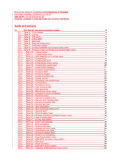
1 norsok Standard D-010 Rev 4, August 2012. 10 wireline operations .. 1. 1. WELL BARRIER SCHEMATICS .. 1. WELL BARRIER ACCEPTANCE CRITERIA .. 1. Well control equipment configuration .. 1. Deployment of 2. Notes .. 2. WELL BARRIER ELEMENTS ACCEPTANCE 3. Potential for compromised well barrier elements probability reducing measures .. 3. Potential for compromised well barrier elements consequence reducing measures .. 4. WELL CONTROL ACTION PROCEDURES AND DRILLS .. 4. Well control action procedures .. 4. Well control action drills .. 5. OTHER 5. Hydrate prevention .. 5. EXAMPLES OF WELL BARRIER SCHEMATIC ILLUSTRATIONS.
2 5. 10 wireline operations General This section covers requirements and guidelines for well integrity Wireline (WL) operations . A Wireline operation is a technique for deployment of various electrical or mechanical downhole tools (logging tools, plugs, packers, perforating guns, shifting tools, pulling tools etc.) on electrical cables, braided cables or slickline. The operations are performed in pressurised wells or in dead wells. The purpose of this section is to describe the establishment of well barriers by use of well barrier elements and additional requirements and guidelines to execute this activity in a safe manner.
3 Well barrier schematics Well barrier schematics (WBS) shall be prepared for each well activity and operation. Samples of well barrier schematics for selected situations are presented at the end of this section ( ). Well barrier acceptance criteria The following list defines specific requirements and guidelines for well barriers: Well control equipment configuration The following basic well control equipment configurations should be used. Note: Additional elements (eg. additional BOP ram functions) should be considered based on each operation specific risk analysis. a) For operations in a surface completed well 1. Pressure control head including a device that will automatically seal of the wellbore in the event the Wireline breaks and is ejected from the wellbore 1.
4 For slickline a stuffing box. 2. For braided or electric cable a stuffing box and sufficient number of flow tubes (grease head) to contain the applicable well pressure taking into account cable size and gas content in the well. 2. Lubricator 3. Wireline BOP. 3. For slickline a slickline ram maintaining pressure from below 4. For braided or electric cable dual rams maintaining pressure from above and below creating a grease chamber between them 4. WL safety head (shear/seal ram with independent hydraulic operation). 1. norsok Standard norsok Standard D-010 Rev 4, August 2012. b) For operations with a riserless lubricator system on a subsea completed well 1.
5 Pressure control head 2. Tool catcher (or tool trap). 3. Cutting/sealing ram or valve 4. Lubricator 5. Upper and lower isolation valves 6. Safety head (shear/seal ram). Deployment of toolstrings Deployment of long Wireline toolstrings (in excess of the available surface lubrication length) may be achieved as follows: a) Use of deployment bar and deployment rams (see WBS examples for one possible configuration). 1. A double block principle (eg. by use of two separate rams) shall be applied for sealing around the deployment bar. b) Use of a downhole lubricator valve (ball type) above (and in addition to) the downhole safety valve 1.
6 The production tubing above the downhole safety valve shall be displaced to an inert fluid 2. The downhole safety valve shall be closed and tested in the direction of flow potential 3. The lubricator valve shall be closed and tested from above to the shut-in wellhead pressure + 70. bar. c) Use of the downhole safety valve with a drop protection function for the downhole safety valve 1. The production tubing above the downhole safety valve shall be displaced to an inert fluid 2. Crosshead circulation via a trip tank will be in place to monitor the volume in the production tubing above the downhole safety valve 3. The downhole safety valve shall be closed and tested in the direction of flow potential 4.
7 The BHA will be handled with a quick release drop table to allow it to be dropped below the xmas tree at any time Notes a) A tool catcher, tool trap or similar device should be used to protect the valve below against damage in the event of accidentally pulling the cable out of the cable head during operation. b) It is acceptable to use another hydraulically remotely operated valve, the HMV, to replace the WL. safety head, provided the valve has documented wire cutting and sealing capabilities according to norsok D-002. c) A double-valve kill inlet connection shall be included in the rig-up. The kill line itself is not required.
8 The valves shall be capable of holding pressure in both directions. The inner valve shall be flanged and have metal to metal seal. The production tree kill wing valve may be used as the inner valve. Both valves shall be leak tested in the direction of flow. A bleed off/pressure monitoring port between the valves or a tested blind cap with bleed off/pressure monitoring port shall be installed. If neither of the valves are remotely controlled, a check valve shall be installed whenever connecting a kill line. d) When rigging up on a well where the primary well barrier (SCSSV) has failed, the WL safety head shall be installed and tested prior to continuing to R/U the remaining Wireline well control equipment.
9 If another valve, a HMV with documented wire cutting capability, is used as WL safety head, then both the primary and secondary barriers shall be tested prior to rigging up. e) The riser/lubricator length between the surface production tree and the WL safety head shall be as short as possible. If the WL BOP is installed high in the rig up configuration ( when rigging up the WL BOP. on drill floor) a separate WL safety head shall be installed close to the surface production tree. f) The number of riser/lubricator connections between the surface production tree and the WL BOP/ WL. safety head are critical and should be kept to a minimum.
10 2. norsok Standard norsok Standard D-010 Rev 4, August 2012. g) All tools or components that the WL safety head may not be able to cut shall be identified prior to start of operation. Contingency procedures and compensating measures shall be in place for how to act when such tools or components are positioned across the WL safety head (ref. and ). h) The shear/seal ram in the LRP is defined as the upper closure device in the secondary well barrier whenever running Wireline in completed SSWs. The same shear/seal requirements therefore apply to the LRP shear/seal ram as to the WL safety head. i) The shear/seal ram in the subsea drilling BOP is defined as the upper closure device in the secondary well barrier whenever a subsea drilling BOP is installed when running Wireline in sub-sea wells.


