Transcription of EN 13445-3:2002 - 64 e stf - standard.no
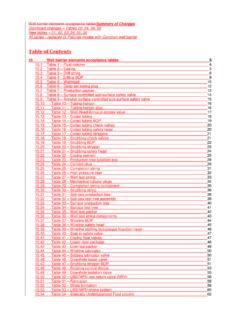
1 EN 13445-3:2002 (E) Issue 18 (2006-02) 3 Flat ends of non-circular or annular 11 Flanges ..148 Specific Specific symbols and abbreviations ..149 Narrow face gasketed flanges ..154 Full face flanges with soft ring type gaskets ..169 Seal welded Reverse narrow face flanges ..173 Reverse full face Full face flanges with metal to metal contact ..179 12 Bolted domed ends ..182 Specific Specific symbols and abbreviations.
2 182 Bolted domed ends with narrow face gaskets ..182 Bolted domed ends with full face 13 Heat Exchanger Tubesheets ..187 Specific Specific symbols and abbreviations ..188 U-tube tubesheet heat exchangers ..190 Fixed tubesheet heat exchangers ..205 Floating tubesheet heat exchangers ..234 Tubesheet characteristic ..253 Maximum permissible tube to tubesheet joint Maximum permissible longitudinal compressive stress for tubes ..261 Design of tubesheet flange extension with a narrow face Design of tubesheet flange extension with a full face gasket.
3 269 Special tube-to-tubesheet welded 14 Expansion bellows ..275 Specific Specific symbols and abbreviations ..277 Conditions of U-shaped unreinforced bellows ..281 U-shaped reinforced bellows ..295 Toroidal bellows ..299b Fabrication ..299h Inspection and Bellows subjected to axial, lateral or angular displacements ..300 15 Pressure vessels of rectangular Specific Specific symbols and abbreviations ..306 Unreinforced vessels.
4 308 Reinforced vessels ..314 Openings ..323 16 Additional non-pressure Specific Specific symbols and abbreviations ..326 Local loads on nozzles in spherical shells ..328 Local loads on nozzles in cylindrical shells ..338 Line loads ..349 Lifting lugs ..356 EN 13445-3:2002 (E) Issue 34 (2008-12) 4 Horizontal vessels on saddle Horizontal vessels on ring supports ..374 Vertical vessels on bracket Vertical vessels with supporting legs.
5 384 Vertical vessels with Vertical vessels with ring supports ..404 Global loads ..415 17 Simplified assessment of fatigue life ..421 Purpose ..421 Specific Specific symbols and abbreviations ..423 Conditions of applicability ..424 General ..425 Determination of allowable number of pressure Assessment Design and manufacture ..451 Testing ..452 18 Detailed assessment of fatigue life.
6 453 Purpose ..453 Specific Specific symbols and abbreviations ..456 Limitations ..459 General ..460 Welded material ..462 Unwelded components and bolts ..467 Elastic-plastic conditions ..470 Fatigue action ..472 Fatigue strength of welded components ..475 Fatigue strength of unwelded Fatigue strength of steel bolts ..503 19 Creep design ..504a Specific definitions ..504a Specific symbols and Design in the creep range .. 504b Nominal Design stress in the creep range.
7 504b Weld joint factor in the creep 504f Pressure loading of predominantly non-cyclic nature in the creep range .. 504g Design procedures for DBF .. 504g 20 Design by experimental methods ..504aa Purpose ..504aa Specific Specific symbols and abbreviations ..504aa General requirements ..504ac Methods .. 504ad Test specifications .. 504af Duplicate or similar parts ..504al 504am 21 Design Rules For Reinforced Flat Walls .. 504ba General .. 504ba Stayed Flat Walls.
8 504ba Specific Definitions for Stayed Flat Walls .. 504ba Required Thickness of Stayed Flat Walls .. 504ba Required Dimensions and Layout of Staybolts and Stays .. 504ba Requirements For Threaded Staybolts .. 504bb Requirements For Welded-in Staybolts And Welded Stays .. 504bb Tables for Stayed Flat 504bc Figures for Stayed Flat Walls .. 504bd 22 Circular flat ends with radial reinforcement EN 13445-3:2002 (E) Issue 34 (2008-12) 4a Specific Specific symbols and abbreviations ..504cc Ends without additional peripheral bending moment.
9 504cd Ends with additional peripheral bending moment ..504cf Openings ..504ch Welds ..504ch Central Ring ..504ci Annex A (normative) Design requirements for pressure bearing welds ..505 Annex B (normative) Design by Analysis - direct route ..529 Annex C (normative) Design by Analysis - method based on stress categories ..550 Annex D (informative) Verification of the shape of vessels subject to external Annex E (normative) Procedure for calculating the departure from the true circle of cylinders and cones ..576 Annex F (normative) Allowable external pressure for vessels outside circularity tolerance.
10 579 Annex G (normative) Alternative design rules for flanges and gasketed flange Annex GA (informative) Alternative design rules for flanges and gasketed flange Annex H (informative) Table H-1 Gasket factors m and Annex I (informative) Additional information on heat exchanger tubesheet Annex J (normative) Alternative methods for the design of heat exchanger Annex K (informative) Additional information on expansion bellows design ..674 Annex L (informative) Basis for design rules related to additional non-pressure loads ..681 Annex M (informative) In service monitoring of vessels operating in fatigue or Annex N (informative) Bibliography to Clause 18.
