Transcription of 117-R90 Commentary on Standard Specifications for …
1 ACI 117R-90. Reapproved 2002. Commentary on Standard Specifications for Tolerances for concrete Construction and Materials (ACI 117-90). Reported by ACI Committee 117. W. Robert Little Russell S. Fling Chairman Chairman, Editorial Subcommittee S. Allen Face Andrawos Morcos B. J. (Duke) Pointer Thomas C. Heist Clark B. Morgan Jr. Dean B. Stephan Jr.*. Richard A. Kaden Harry M. Palmbaum Eldon Tipping Ross Martin William S. Phelan Carl S. Togni Peter Meza Joe V. Williams, Jr. This report is a Commentary on the Standard Specifications for Tolerances the tolerances given are Standard or usual tolerances that ap- for concrete Construction and Materials. It is intended to be used with ACI ply to various types and uses of concrete construction. They 117 for clarity of interpretation and insight into the intent of the committee regarding the application of the tolerances set forth therein. are based upon normal needs and common construction tech- niques and practices. Specific tolerances at variance with the Keywords: bending (reinforcing steels); building codes; concrete construc- Standard values can cause both increases and decreases in the tion; concrete piles; concretes; floors; formwork (construction); masonry; cost of construction.
2 Mass concrete ; piers; precast concrete ; prestressed concrete ; reinforcing The required degree of accuracy of performance depends steels, Specifications ; splicing; standards ; tolerances (mechanics). on the interrelationship of several factors: INTRODUCTION Structural strength and function requirements This Commentary pertains to Standard Specifications for The structure must be safe and strong, reflecting the design Tolerances for concrete Construction and Materials (ACI- assumptions, and accurate enough in size and shape to do the 117). The purpose of the report is to provide graphic and job for which it was designed and constructed. written interpretations for the specification and its application. No structure is exactly level, plumb, straight, and true. Esthetics Fortunately, such perfection is not necessary. Tolerances are The structure must satisfy the appearance needs or wishes a means to establish permissible variation in dimension and of the owner and the designer. location, giving both the designer and the contractor param- eters within which the work is to be performed.
3 They are the Economic feasibility means by which the designer conveys to the contractor the The specified degree of accuracy has a direct impact on the performance expectations upon which the design is based or cost of production and the construction method. In general, the use of the project requires. Such specified tolerances the higher degree of accuracy required, the higher the cost of should reflect design assumptions and project needs, being obtaining it. neither overly restrictive nor lenient. Necessity rather than desirability should be the basis of selecting tolerances. Relationship of all components As the title Standard Specifications for Tolerances for The required degree of accuracy of individual parts can be concrete Construction and Materials (ACI 117) implies, influenced by adjacent units and materials, joint and connec- tion details, and the possibility of the accumulation of toler- ACI Committee Reports, Guides, Standard Practices, and ances in critical dimensions.
4 Commentaries are intended for guidance in planning, design- ing, executing, or inspecting construction and in preparing Specifications . Reference to this document shall not be *Chairman during initial developement of this document made in the Project Documents. If items found in these Copyright 1990, American concrete Institute. documents are desired to be a part of the Project Documents, All rights reserved including rights of reproduction and use in any form or by any means, including the making of copies by any photo process, or by electronic or they shall be phrased in mandatory language and incorporated mechanical device, printed, written, or oral, or recording for sound or visual reproduc- tion or for use in any knowledge or retrieval system or device, unless permission in in the Project Documents. writing is obtained from the copyright proprietors. 117R-1. 117R-2 ACI COMMITTEE REPORT. Construction techniques General building ACI 302, 303, 304, 318, 347. The feasibility of a tolerance depends on available crafts- Special structures ACI 307, 313, 316, 325, 332, 334, manship, technology, and materials.
5 344, 345, 349, 350, 357, 358. Precast construction ACI 347. Properties of materials Masonry construction ACI 531. The specified degree of accuracy for shrinkage and pre- Materials ACI 211, 223, 302, 304, 315, 318, stressed camber should recognize the degree of difficulty of 531, 543. predetermining deflection due to shrinkage and prestressed camber. TABLE OF CONTENTS. Compatibility Introduction, p. 117R-1. Designers are cautioned to use finish and architectural de- tails that are compatible with the type and anticipated meth- Section 1 General requirements, p. 117R-2. od of construction. Finish and architectural details used Section 2 Materials, p. 117R-4. should be compatible with the concrete tolerances which are achievable. Section 3 Foundations, p. 117R-5. Job conditions Section 4 Cast-in-place concrete for buildings, Unique job situations and conditions must be considered. p. 117R-5. The designer must specify and clearly identify those items that require either closer or more lenient tolerances as the Section 5 Precast concrete , p.
6 117R-8. needs of the project dictate. Section 6 Masonry, p. 117R-10. Measurement Section 7 Cast-in-place, vertically slipformed Mutually agreed-upon control points and bench marks structures, p. 117R-10. must be provided as reference points for measurements to es- tablish the degree of accuracy of items produced and for ver- Section 8 Mass concrete structures other than build- ifying the tolerances of the items produced. Control points ings, p. 117R-10. and bench marks should be established and maintained in an Section 9 Canal lining, p. 117R-10. undisturbed condition until final completion and acceptance of the project. Section 10 Monolithic siphons and culverts, p. 117R-10. Project document references ACI specification documents The following American Section 11 Cast-in-place bridges, p. 117R-10. concrete Institute documents provide mandatory require- ments for concrete construction and may be referenced in the Section 12 Pavement, p. 117R-10. Project Documents: Section 13 Chimneys and cooling towers, p.
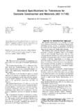
7 117R-11. ACI 117 Standard Specifications for Tolerances Section 14 Cast-in-place nonreinforced pipe, p. 117R-11. for concrete Construction and Materials Section 15 References, p. 117R-11. ACI 301 Specifications for Structural concrete for Buildings SECTION 1 GENERAL REQUIREMENTS. ACI specification for concrete Masonry Definitions Construction Bowing See Fig. Flatness See Fig. ACI informative documents ACI Committee Reports, Lateral alignment See Fig. Guides, Standard Practices, and Commentaries are intended Level alignment See Fig. for guidance in designing, planning, executing, or inspecting Relative alignment See Fig. construction, and in preparing plans and Specifications . Ref- Vertical alignment See Fig. erence to these Reports, Guides, and Standard Practices Warping See Fig. should not be included in the Project Documents. If the Ar- Level alignment, lateral alignment, and vertical alignment chitect/Engineer desires to include items found in these ACI are used to establish a tolerance envelope within which per- documents in the Project Documents, they should be re- missible variations can occur.
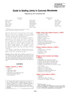
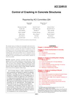
8 Relative alignment, in addi- phrased in mandatory language and incorporated into the tion to designating allowable relative displacements of Project Documents. elements, is used to determine the rate of change of adjacent The documents of the following American concrete Insti- points (slope tolerance) occurring within the tolerance enve- tute Committees cover practice, procedures, and state-of- lope. In this fashion the slope and smoothness of surfaces the-art guidance for the categories of construction as listed. and lines within a tolerance envelope are controlled. Abrupt TOLERANCES 117R-3. Fig. Level alignment Fig. Bowing Fig. Relative alignment Fig. Flatness Fig. Vertical alignment Fig. Lateral alignment Fig. Warping 117R-4 ACI COMMITTEE REPORT. Fig. (a) Reinforcement placement Fig. Reinforcement placement, longitudinal location Fig. (b) and (b) Reinforcement placement Fig. Reinforcement placement, embedment and laps SECTION 2 MATERIALS. Reinforcement In the absence of specific design details shown or specified on the contract documents, CRSI MSP-l, Appendix D, should be followed by estimators, detailers, and placers.
9 And The tolerance for placing reinforcing steel is predicated upon measurements of the formed surfaces for quality control during construction and from the resulting Fig. (a) Reinforcement placement surfaces for forensic analysis. It consists of an envelope with an absolute limitation on one side of the envelope deter- mined by the limit on the reduction in cover. See Fig. (a), (b), (a), and (b). and The spacing tolerance of reinforcing con- sists of an envelope with an absolute limitation on one side of the envelope determined by the limit on the reduction in distance between reinforcement. In addition, the allowable tolerance on spacing shall not cause a reduction in the spec- ified number of reinforcing bars utilized. See Fig. and The vertical deviation tolerance should be con- sidered in establishing minimum prestressing tendon covers, Fig. and Reinforcement placement particularly in applications exposed to deicer chemicals or salt water environments where use of additional cover is rec- ommended to compensate for placing tolerances.
10 Slab be- changes, offsets, sawtoothing, sloping, etc., of lines and sur- havior is relatively insensitive to horizontal location of faces properly located within a tolerance envelope may be tendons. objectionable when exposed to view. The acceptable relative and The tolerance for the location of the ends alignment of points on a surface or line is determined by us- of reinforcing steel is determined by these two sections. See ing a slope tolerance. Fig. and TOLERANCES 117R-5. concrete Where the specification has specified slump as a maximum, the project Specifications should provide for the addition of water at the jobsite for slump adjustment. This is because the concrete must be batched at a lesser slump to avoid rejection because of a lack of a plus tolerance for the slump. The water added at the jobsite must be within the wa- ter/cement limitations of the Specifications or approved mix- ture proportions. Flowable concrete achieved by the incorporation of high range water reducers (HRWR) (superplasticizers), are diffi- Fig.